The Complete Guide to Calibrate a Viscometer
- Section 1: The Fundamentals of Viscometer Calibration
- Section 2: The Essential Toolkit for Professional Viscometer Calibration
- Section 3: Step-by-Step Guide: Calibrating Rotational Viscometers
- Section 4: Step-by-Step Guide: Calibrating Glass Capillary Viscometers (e.g., Ubbelohde)
- Section 5: Step-by-Step Guide: Calibrating Falling Ball Viscometers
- Section 6: Compliance and Quality Assurance: Meeting International Standards
- Section 7: Troubleshooting Common Calibration Errors
- Conclusion
|
|

Meta Description: Master viscometer calibration with our expert guide. Learn step-by-step procedures for rotational, capillary, and falling ball viscometers, understand ISO/ASTM standards, and choose the right NIST-traceable fluids for guaranteed accuracy in your lab.
In industries ranging from pharmaceuticals and petrochemicals to food production and coatings, viscosity is a critical parameter. It dictates flow behavior, ensures product stability, and defines the end-user experience. In these demanding fields, viscosity is not just a number—it is a cornerstone of quality, performance, and safety. However, the integrity of this crucial measurement hinges entirely on one process: calibration. An uncalibrated viscometer does not simply produce an incorrect reading; it introduces significant business risk, potentially leading to inconsistent product quality, failed batches, costly recalls, and non-compliance with regulatory standards.
This guide serves as the definitive, comprehensive resource for laboratory professionals, quality control managers, and procurement specialists. By following the detailed procedures outlined here, you can ensure the integrity of your viscosity data, optimize your processes, and maintain strict adherence to global quality standards. This report will explore the fundamental principles of calibration, provide step-by-step instructions for the major types of viscometers, and offer expert guidance on troubleshooting and compliance, empowering your laboratory to achieve accurate, repeatable, and defensible results.
Section 1: The Fundamentals of Viscometer Calibration
1.1. Why Calibration is Non-Negotiable for Quality Control and Compliance
At its core, calibration is the process of verifying and adjusting an instrument to ensure its measurements are accurate and consistent by comparing it to a known, traceable standard. This process is essential because all measurement instruments, including viscometers, are subject to “drift” over time due to mechanical wear, environmental factors, and frequency of use. Without regular calibration, these instruments gradually become less accurate, compromising the reliability of their data.
The stakes of using an uncalibrated viscometer are high. Inaccurate viscosity data can severely impact product quality, leading to variations between batches that affect everything from the texture of a food product to the efficacy of a pharmaceutical formulation. In regulated industries such as pharmaceuticals, food and beverage, and cosmetics, proper calibration is a mandatory component of Good Manufacturing Practices (GMP) and compliance with standards set by organizations like the International Organization for Standardization (ISO), ASTM International, the U.S. Food and Drug Administration (FDA), and the United States Pharmacopeia (USP).
For scientific instrument importers and distributors, the value of calibration extends directly to their business model. Selling a properly calibrated instrument, or offering accredited calibration services, is a significant value-add. It provides customers with immediate confidence in the equipment’s performance, reduces their operational and regulatory risks, and guarantees that the instrument meets international quality expectations from the moment it is unboxed.
1.2. Calibration, Verification, and Adjustment: Understanding the Key Differences
While often used interchangeably, the terms calibration, verification, and adjustment have distinct meanings in a metrology context. Understanding these differences is crucial for effective laboratory quality management.
-
- Calibration: This is a formal, high-level operation that compares an instrument’s performance against a highly accurate, traceable reference standard across its entire measurement range. The process is typically performed by a specialized, accredited laboratory and results in a detailed calibration certificate that documents the instrument’s measured error and measurement uncertainty.9 If the instrument is found to be outside its specified tolerances, an adjustment is performed as part of the calibration service.
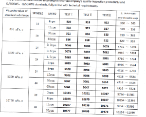
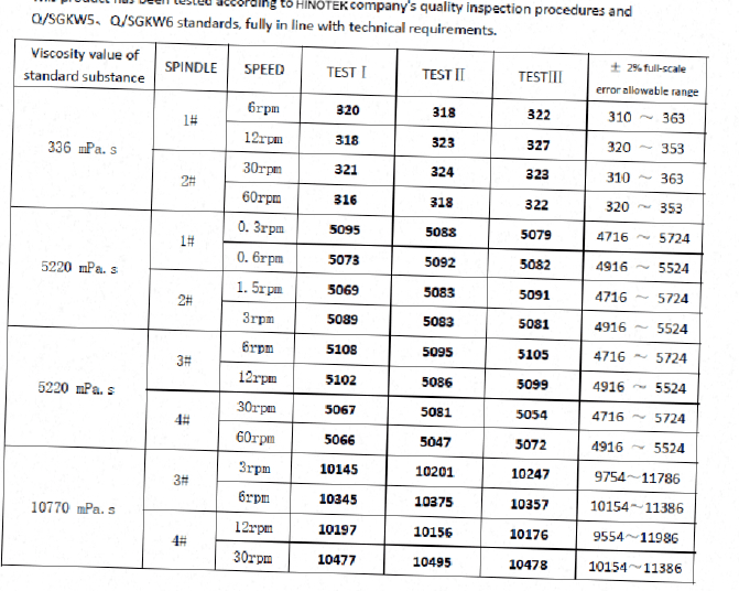
- Verification (or Calibration Check): This is a more routine check, often performed by the end-user in their own lab, to confirm that the instrument continues to operate within its specified tolerance limits. It typically involves measuring a single known reference standard fluid under controlled conditions. If the instrument fails this verification, it is a clear indicator that it requires professional service and a full recalibration. Normally We (HINOTEK) will provide below Verification for our NDJ Series Viscometer:
Certification - Adjustment: This is the physical or electronic act of altering an instrument to correct for a measurement error that was identified during calibration. Many modern digital viscometers feature built-in adjustment functions that allow a trained user or service technician to bring the instrument’s readings back into alignment with the reference standard.
|
|
This two-tiered system of quality assurance—frequent, user-led verification to monitor for drift, and less frequent, formal calibration to re-establish baseline accuracy—is a cornerstone of robust quality systems. Lab managers must plan and budget for both activities to ensure uninterrupted data integrity.
1.3. Establishing a Calibration Schedule: How Often is Enough?
The optimal calibration frequency for a viscometer is a risk-based decision, not a one-size-fits-all rule. While most instrument manufacturers and calibration service providers recommend a standard interval of once per year as a starting point, the ideal schedule depends on a variety of factors.
Key factors influencing the calibration interval include:
- Regulatory and Quality System Requirements: GMP-compliant environments or labs adhering to strict ISO standards may mandate more frequent calibration, such as every six months.
- Frequency and Criticality of Use: An instrument that is used daily for critical quality control release testing will likely require more frequent verification and calibration than one used intermittently for research and development.
- Instrument Performance History: A new instrument should be monitored closely. If historical data from verifications and calibrations show the instrument to be highly stable, the interval may be extended. Conversely, if an instrument shows a tendency to drift, the interval should be shortened.
- Environmental Conditions: Viscometers operating in harsh environments with significant vibrations, temperature fluctuations, or humidity are more susceptible to drift and may require more frequent calibration.
A formal, documented calibration program is a fundamental requirement for any laboratory operating under a quality system like ISO/IEC 17025. Vague scheduling statements such as “as needed” are unacceptable for audits unless they are supported by a documented procedure and data justifying the interval.
Section 2: The Essential Toolkit for Professional Viscometer Calibration
2.1. Choosing the Right Viscosity Standard Fluid: A Deep Dive
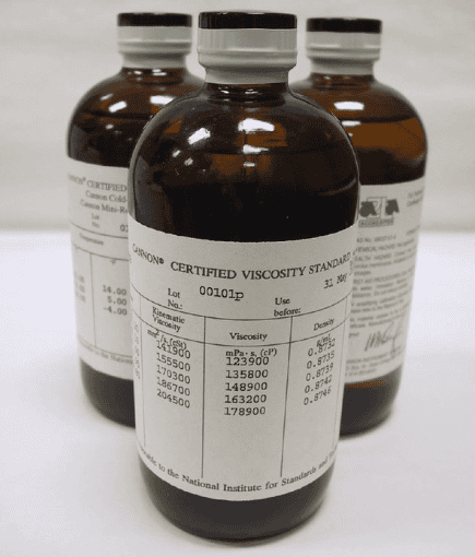
Viscosity standard fluids are the cornerstone of any calibration or verification procedure. These are highly stable, Newtonian fluids with precisely certified viscosity values at specific temperatures, serving as the authoritative benchmark against which an instrument’s performance is measured.
|
|
Types of Viscosity Standard Fluids:
- Silicone Fluids: These are the most common standards for calibrating rotational viscometers. They are prized for their excellent temperature stability and Newtonian behavior, meaning their viscosity remains constant regardless of the shear rate applied. This predictable behavior makes them ideal as a reference material. They are available in a vast range of viscosity values, from very low to very high.
- Mineral Oil Fluids: Also known as hydrocarbon oils, these standards are widely used across many industries, particularly in petrochemical applications and for calibrating specific instrument types like cone-and-plate viscometers.
- Specialty Fluids: A variety of specialized standards exist for specific applications, including high-temperature fluids for use with accessories like the Brookfield Thermosel, low-temperature standards for cold-cranking simulator tests in the automotive industry, and standards formulated for medical or clinical viscometry.
When selecting a standard, its viscosity value should align with the typical measurement range of the samples being tested and be appropriate for the viscometer model (e.g., LV, RV, HA, HB series viscometers have different torque springs and are designed for low, medium, and high viscosity ranges, respectively). For a comprehensive verification, best practice dictates using multiple standards to check the instrument’s performance at low, middle, and high points of its operational torque range.
2.2. The Critical Importance of NIST Traceability and Certified Standards
The terms “certified” and “NIST traceable” are fundamental to the concept of measurement confidence and are non-negotiable in regulated and quality-driven environments.
What is NIST Traceability?
NIST traceability provides documented, objective proof that a measurement can be linked back to a national or international standard through an unbroken chain of comparisons, each with a stated uncertainty. For viscosity, the primary standard recognized internationally is pure water, which has a defined kinematic viscosity of 1.0034 mm2/s (or centistokes, cSt) and a dynamic viscosity of 1.0016 mPa·s (or centipoise, cP) at 20°C. Certified viscosity standards are calibrated against master viscometers, which in turn are calibrated against this primary water standard, creating the traceable link.
Why Traceability Matters:
- Data Integrity and Comparability: Traceability ensures that a viscosity measurement made in a lab in one part of the world is accurate and comparable to a measurement made in another, fostering global trade and scientific collaboration.
- Regulatory Compliance: Quality standards like ISO/IEC 17025, which governs calibration laboratories, explicitly require metrological traceability. It is an essential requirement for passing audits in pharmaceutical, medical device, and aerospace industries.
- Commercial Confidence: For importers, distributors, and manufacturers, offering products and standards with NIST traceability is a powerful statement of quality. It assures customers that the products meet the highest global standards for measurement accuracy.
2.3. Best Practices for Handling, Storing, and Disposing of Standard Fluids
The accuracy of a standard fluid can be easily compromised by improper handling. Following strict protocols is essential to maintain its integrity.
- Handling: The primary goal is to prevent contamination. Never pour used standard fluid back into its original container, as this will contaminate the entire stock. When pouring the fluid into a beaker for measurement, do so carefully to minimize the introduction of air bubbles, which can cause erroneous readings.
- Storage: Standard fluids should be stored in their original, tightly sealed containers in a temperature-controlled environment, away from direct sunlight, as specified by the manufacturer.
- Shelf Life: Viscosity standards have a limited shelf life and an explicit expiration date printed on their certificate of calibration. For example,
2.4. Ancillary Equipment: The Unsung Heroes of Accuracy
An accurate calibration is the result of a controlled system, where every component contributes to the final result. The viscometer itself is only one part of this system.
- Temperature Control: Viscosity is highly dependent on temperature; even a small deviation can cause a significant change in a fluid’s viscosity. Therefore, a high-precision circulating water bath or another temperature control accessory is absolutely essential. The system must be capable of maintaining the standard fluid at its certified temperature with very tight stability, for example, 25.0°C ± 0.1°C or better.
- Calibrated Thermometer: The accuracy of the temperature bath must be confirmed with a calibrated thermometer that is itself traceable to national standards. Using an uncalibrated thermometer to check the bath temperature breaks the chain of traceability.
- Calibrated Timer: For manual methods like capillary or falling ball viscometry, which rely on measuring time, a calibrated, high-precision stopwatch or electronic timer is critical.
- Stable Environment: The viscometer must be placed on a solid, level, and vibration-free surface. Vibrations from other lab equipment can interfere with the sensitive torque measurement of a rotational viscometer, leading to unstable readings.
This concept of an interconnected “Total Calibration Ecosystem” is vital. A state-of-the-art viscometer will produce worthless data if it is checked against an expired standard in a temperature-uncontrolled environment. For laboratories, this means procurement must consider the entire system. For distributors, this presents an opportunity to move beyond selling a single instrument and instead offer a complete, validated solution package—including the viscometer, a temperature bath, and a starter kit of certified standards—thereby simplifying the customer’s path to accurate measurements.
Section 3: Step-by-Step Guide: Calibrating Rotational Viscometers
3.1. Principle of Operation: Understanding Torque and Resistance
Rotational viscometers are among the most common instruments for measuring viscosity. Their principle of operation is based on measuring the viscous drag of a fluid against a rotating sensor, known as a spindle. The instrument rotates the spindle at a precise, constant speed while it is immersed in the test fluid. The fluid’s resistance to this rotation creates a torque on the spindle. The viscometer measures this torque, which is directly proportional to the fluid’s dynamic viscosity.
The final viscosity value is calculated based on the measured torque, the rotational speed (RPM), and the geometry of the specific spindle being used, which is represented by a Spindle Multiplier Constant (SMC) or “factor”. Different viscometer models (e.g., LV, RV, HA, HB) are equipped with different calibrated torque springs, allowing them to accurately measure distinct viscosity ranges—from low-viscosity solutions to thick pastes and gels.
3.2. Pre-Calibration Checklist: Setting the Stage for Success
A successful calibration begins with meticulous preparation. Rushing this stage is a common source of error.
- Environment: Position the viscometer on a heavy, stable lab bench away from sources of vibration like centrifuges, pumps, or heavy foot traffic. The surface must be perfectly level.
- Instrument Setup: Assemble the laboratory stand according to the manufacturer’s instructions. Mount the viscometer and use the integrated bubble level to ensure it is perfectly horizontal. Adjust the leveling feet on the stand as needed.
- AutoZero (Digital Models): This is a critical first step for digital viscometers. With no spindle attached, navigate to the AutoZero function on the instrument and run it. This process zeroes the torque sensor, establishing an accurate baseline for measurement. Do not touch or disturb the instrument during this procedure.
- Spindle Inspection: Carefully inspect the spindle you intend to use. It must be perfectly clean, dry, and straight. Any bend in the shaft or damage to the sensing surface will introduce significant errors.
- Temperature Stabilization: This is arguably the most critical preparation step. Pour the viscosity standard fluid into a 600 mL low-form Griffin beaker (the standard container for this procedure). Place the beaker in the temperature-controlled bath. Allow the fluid to reach and stabilize at the certified temperature (e.g., 25.0°C). This process can take 30 to 60 minutes, or even longer for high-viscosity fluids. To ensure complete thermal equilibrium, the spindle and the viscometer’s guard leg (if used) should also be immersed in the fluid during this time.
3.3. Detailed Calibration Procedure: From Spindle Selection to Data Logging
Follow these steps for a precise and repeatable verification of your rotational viscometer.
- Step 1: Select Spindle and Speed. The objective is to choose a spindle and speed combination that results in a torque reading between 10% and 100% of the instrument’s full-scale range. If you have an approximate idea of the standard’s viscosity, you can use the instrument’s factor tables or AUTO RANGE function to select an appropriate starting point. If the viscosity is unknown, some initial trial and error may be necessary.
- Step 2: Attach the Spindle. Gently lift the viscometer’s coupling nut with one hand while carefully screwing the spindle on with the other. Note that Brookfield spindles use a left-hand thread. Avoid applying any upward or sideways force on the instrument’s pivot assembly, as it is a delicate, high-precision component.
- Step 3: Immerse the Spindle. Lower the viscometer head until the surface of the standard fluid is level with the immersion groove machined into the spindle’s shaft. If using an LV or RV model, the guard leg should be attached to the viscometer and fully immersed in the fluid. Visually inspect the spindle surface for any trapped air bubbles and gently move the spindle to dislodge them if necessary.
- Step 4: Run the Test. Turn on the viscometer’s motor. Allow the reading on the display to stabilize. The time required for stabilization will vary depending on the fluid’s viscosity and the rotational speed. As a rule of thumb, the spindle should be allowed to complete at least five full rotations before a reading is considered stable.
- Step 5: Record the Reading. Once the displayed viscosity (in cP or mPa·s) and the % torque value are stable, record both values in your calibration log.
- Step 6: Repeat for Verification. To ensure the instrument is performing correctly across its range, it is best practice to repeat the measurement at two additional speeds that yield different torque values (e.g., one that gives a low-range torque of 20-30% and one that gives a high-range torque of 70-90%).
- Step 7: Clean Up. After completing all measurements, stop the motor, raise the viscometer head, and carefully remove the spindle. Thoroughly clean the spindle and guard leg with an appropriate solvent and dry them completely before storage.
3.4. Calculating Accuracy and Defining Acceptance Criteria
Determining whether your viscometer has “passed” or “failed” the verification check requires a simple calculation based on the combined tolerances of the instrument and the standard fluid.
The total allowable error is the sum of two components:
- Instrument Accuracy: This is defined as ±1% of the Full-Scale Range (FSR) for the specific spindle and speed combination being used.
- Standard Fluid Accuracy: The accuracy of the certified reference material itself, which is typically ±1% of its stated viscosity value.
To calculate the FSR, you can use one of two methods:
- For Digital Models: Enter the spindle code and RPM, then press the “AUTO RANGE” key. The value displayed on the screen is the FSR in cP.
- For Dial Reading Models: The FSR is equal to the spindle’s factor multiplied by 100.
The acceptance criterion is that the observed viscosity reading from your instrument must fall within the range defined by: ** ±**.15 If your reading falls outside of this calculated range, the instrument has failed the verification and should be flagged for professional service and recalibration.
The following table provides a practical, step-by-step example of this calculation, which is a common point of confusion for many users. It demystifies the process and provides a clear template for laboratory technicians.
| Parameter | Example Value / Calculation | Source / Explanation |
| Viscometer Model | Brookfield RVDV-I+ | |
| Spindle Used | RV#3 | |
| Speed (RPM) | 2 RPM | |
| Viscosity Standard | 5000 cP General Purpose Silicone Fluid | |
| Certified Value of Standard | 4850 cP @ 25°C | |
| 1. Calculate Full Scale Range (FSR) | FSR=TK×SMC×RPM10,000=1.0×10×210,000=50,000 cP | Formula from Brookfield manual. TK=1.0 for RV models, SMC=10 for the RV#3 spindle. |
| 2. Calculate Instrument Accuracy | ±1% of FSR =0.01×50,000 cP=±500 cP | Standard instrument accuracy specification. |
| 3. Calculate Fluid Accuracy | ±1% of Certified Value =0.01×4850 cP=±48.5 cP | Standard fluid accuracy specification. |
| 4. Calculate Total Allowable Error | Instrument Accuracy + Fluid Accuracy = 500 cP + 48.5 cP = ±548.5 cP | The sum of the individual tolerances. |
| 5. Determine Acceptance Range | Certified Value ± Total Error = 4850 ± 548.5 cP = 4301.5 to 5398.5 cP | The final acceptable range for the observed reading. |
| Conclusion | If the viscometer’s stable reading falls within this range, its calibration is verified as satisfactory. |
Section 4: Step-by-Step Guide: Calibrating Glass Capillary Viscometers (e.g., Ubbelohde)
4.1. Principle of Operation: The Physics of Kinematic Viscosity and Flow Time
Glass capillary viscometers, such as the Ubbelohde or Cannon-Fenske types, operate on a fundamentally different principle than rotational viscometers. They measure kinematic viscosity, which is the measure of a fluid’s inherent resistance to flow under the force of gravity. The procedure involves measuring the time it takes for a fixed, known volume of fluid to pass through a long, narrow capillary of a precise and known diameter.
This measurement is governed by the Hagen-Poiseuille law for laminar flow. In its simplified form for these instruments, the kinematic viscosity (ν) is directly proportional to the measured flow time (t). The constant of proportionality (K) is the viscometer constant, a unique value for each individual glass viscometer that depends on its precise geometric dimensions. The governing equation is simply:
ν=K×t The process of calibration for a glass capillary viscometer is, therefore, the precise and traceable determination of this viscometer constant, K.
4.2. Calibration Setup: Using Master Viscometers and Reference Liquids
The calibration of a glass capillary viscometer is a high-precision task that establishes its traceability to international standards. This is typically not a routine user task but one performed by accredited calibration laboratories. The foundational method is the “step-up” procedure described in ASTM D2162.
This chain of calibration begins with the primary standard, pure water.
- Special, high-accuracy master viscometers (which have a very long capillary to minimize error) are calibrated using pure water at 20°C.
- These water-calibrated master viscometers are then used to determine the precise kinematic viscosity of a series of stable oil standards.
- These certified oil standards can then be used to calibrate routine laboratory viscometers, like those sold by HINOTEK.
The essential equipment for this process includes a set of calibrated reference viscometers, a viscometric bath with exceptional temperature stability (e.g., ±0.01°C), a certified and calibrated thermometer, and a calibrated, high-resolution stopwatch or electronic timer.
4.3. Detailed Calibration Procedure: A Guide to Precision Measurement
The following procedure outlines how a viscometer constant is determined.
- Step 1: Setup. The test viscometer and at least two reference viscometers of the same size are placed in appropriate holders within the temperature-controlled bath. It is critical that the viscometers are mounted perfectly vertically, as any tilt will affect the gravitational driving force and invalidate the measurement.
- Step 2: Fill. The viscometers are filled with the chosen standard liquid to the specified fill line, taking extreme care to avoid introducing any particulate matter or air bubbles, which could obstruct the capillary.
- Step 3: Equilibrate. The filled viscometers are allowed to sit in the bath for a sufficient period (e.g., 10 to 15 minutes) to ensure the liquid has reached complete thermal equilibrium with the bath fluid.
- Step 4: Measure Flow Time. Using gentle suction (often from a pipette bulb), the liquid is drawn up through the capillary until its meniscus is above the upper timing mark (M1).
- Step 5: Release and Time. The suction is removed, and the liquid is allowed to flow freely down the capillary under gravity. The stopwatch is started at the exact moment the leading edge of the meniscus passes the M1 mark and is stopped at the exact moment it passes the lower timing mark (M2).
- Step 6: Repeat. This flow time measurement is repeated multiple times (typically 3 to 5) to ensure high precision. The results are checked for repeatability; the difference between the longest and shortest flow times should be extremely small, often less than 0.2% of the average time, to be considered valid.
4.4. The Calculations: Determining the Viscometer Constant (K)
Once a set of precise and repeatable flow times has been collected, the viscometer constant is calculated.
- Average Flow Time: First, the average flow time (tavg) is calculated from the multiple runs.
- Calculate Constant: The constant for the test viscometer (Ktest) is determined by comparing its average flow time (ttest) with the average flow time of a reference viscometer (tref) using the same liquid. If the reference viscometer’s constant (Kref) is known, the test constant can be calculated. The fundamental relationship is K=νstd/tavg. For highest accuracy, international standards like ISO 3105 and ASTM D446 provide more complex formulas that account for factors like kinetic energy corrections.
- Gravity Correction: The viscometer constant is directly influenced by the local acceleration of gravity (g). If the viscometer is calibrated in one location and used in another where gravity is different by more than 0.1%, a correction must be applied to the constant: Ctest=Ccal×(gcal/gtest).
The calibration of a glass capillary viscometer is fundamentally different from that of a rotational instrument. It is not a routine check of an electronic system but the determination of an intrinsic physical property of the glassware itself. Once this constant is certified by an accredited lab, it remains valid for a very long time, provided the viscometer is not physically damaged or subjected to harsh chemical cleaning that could etch the glass capillary. This makes
pre-calibrated capillary viscometers sold with an ISO/IEC 17025 certificate a significant value proposition. For the end-user, this means the instrument is ready for traceable, compliant measurements immediately, saving them the time, complexity, and expense of performing the initial calibration themselves.
Section 5: Step-by-Step Guide: Calibrating Falling Ball Viscometers
5.1. Principle of Operation: Applying Stokes’ Law for Viscosity Measurement
The falling ball viscometer, often referred to by the Hoeppler principle, measures dynamic viscosity by timing the descent of a sphere through a column of the sample liquid. The ball falls under the influence of gravity, but its descent is opposed by the buoyant force and the viscous drag of the fluid. When these forces balance, the ball reaches a constant terminal velocity.
The dynamic viscosity (η) is calculated using a formula derived from Stokes’ Law, which incorporates the fall time (t), the densities of the ball (ρball) and the liquid (ρliquid), and a specific ball constant (K) that accounts for the precise geometry of the ball and the fall tube. The equation is:
η=K×(ρball−ρliquid)×t
Calibration of this instrument involves verifying its performance by measuring a reference standard fluid with a known viscosity and density, and comparing the measured fall time to the theoretically expected fall time.
5.2. Detailed Calibration Procedure: From Ball Selection to Fall Time Measurement
Precision in this method relies on careful setup and execution.
- Step 1: Clean and Prepare. The fall tube and the selected ball must be scrupulously clean and completely dry. Any residue will affect the ball’s descent.
- Step 2: Select Ball. These viscometers typically come with a set of calibrated balls of different materials or sizes (e.g., a set of 6). The appropriate ball is selected based on the expected viscosity of the standard fluid to ensure the fall time is long enough for accurate measurement but not impractically slow.
- Step 3: Fill Tube. Fill the measuring tube with the certified standard fluid. Pour carefully to avoid introducing air bubbles or particulates, which can impede the ball’s path.
- Step 4: Equilibrate. Place the filled tube into its outer jacket, which is connected to a circulating temperature bath. Allow the entire assembly to reach and stabilize at the desired test temperature. The tube is mounted at a specific angle (e.g., 80° from horizontal for a Hoeppler viscometer) to ensure a controlled rolling-and-sliding motion.
- Step 5: Measure Fall Time. Release the ball from its starting position at the top of the tube. Using a calibrated stopwatch, precisely measure the time it takes for the ball to travel between two engraved fiduciary marks on the fall tube.
- Step 6: Repeat. After the ball reaches the bottom, the entire tube assembly can be inverted to return the ball to the starting position. The measurement should be repeated several times to ensure the fall time is reproducible.
5.3. Calculating Dynamic Viscosity and Verifying Accuracy
Verification involves checking the measured results against the known properties of the standard fluid.
- Using the certified dynamic viscosity of the standard fluid (ηstd), its density at the test temperature (ρliquid), the known density of the ball (ρball), and the ball’s constant (K), rearrange the formula to calculate the theoretically expected fall time (texpected).
- Compare this expected fall time to the average measured fall time (tmeasured).
- The deviation between the measured and expected times should be within the combined tolerance limits of the instrument and the standard fluid to pass the verification check.
A critical operational detail often overlooked with falling ball viscometers is the explicit need for the density of the liquid being tested. Unlike rotational or capillary viscometers, where density is not part of the primary calculation, here it is a required input. This means that for an accurate calibration or sample measurement, the user must first determine the density of their fluid at the precise test temperature using a separate instrument, such as a density meter or a pycnometer. This is a key piece of practical advice for users and presents a cross-selling opportunity for distributors, who can offer a complete measurement solution of both a viscometer and a density meter.
Section 6: Compliance and Quality Assurance: Meeting International Standards
6.1. Understanding ISO/IEC 17025: The Gold Standard for Calibration Laboratories
ISO/IEC 17025, “General requirements for the competence of testing and calibration laboratories,” is the premier international standard for laboratories performing calibration and testing. It is the highest level of quality attestation a calibration provider can achieve.
Accreditation to this standard signifies that a laboratory has not only implemented a rigorous quality management system but has also proven its technical competence to perform specific calibrations and produce precise, accurate, and traceable results. For a customer, choosing a calibration service that is accredited to ISO/IEC 17025 provides the ultimate confidence in the results. The calibration certificates issued by such labs are considered audit-proof and are recognized globally, which is essential for companies operating in regulated sectors or exporting to international markets.
6.2. Navigating Key ASTM Standards: A Focus on ASTM D2162
ASTM International provides several foundational standards for viscosity measurement, particularly within the petroleum, chemical, and materials industries.
- ASTM D2162: This is the “Standard Practice for Basic Calibration of Master Viscometers and Viscosity Oil Standards”. It is a critical document that outlines the “step-up” methodology for establishing a traceable chain of viscosity standards. It details how to calibrate master viscometers using the primary standard (water) and then use those master instruments to certify secondary oil standards.
- ASTM D445: This is the “Standard Test Method for Kinematic Viscosity of Transparent and Opaque Liquids.” It is the workhorse method for routine viscosity measurements using calibrated glass capillary viscometers.
- ASTM D446: This standard provides the “Specifications and Operating Instructions for Glass Capillary Kinematic Viscometers,” defining the design and operational requirements for these instruments.
Adherence to these ASTM standards ensures that calibration and measurement methods are standardized and robust, producing results that are reliable and accepted worldwide.
6.3. In-House Verification vs. Professional Calibration Services: A Decision Guide for Lab Managers
Laboratories face the decision of how to manage their calibration program: perform checks in-house, outsource to a professional service, or use a combination of both.
- In-House Verification:
- Pros: Convenient for performing frequent checks to monitor for instrument drift, with a lower apparent cost per event.
- Cons: This is limited to verification, not a full, accredited calibration. It requires significant investment in trained personnel, certified reference standards, and a highly controlled environment (temperature baths, etc.).
- Professional (Outsourced) Calibration:
- Pros: Provides a full, traceable calibration with an accredited certificate (e.g., to ISO/IEC 17025). The service includes inspection, cleaning, adjustment, and repair, and provides the audit-proof documentation required by quality systems. It removes the technical burden from internal staff.
- Cons: Higher cost per event and potential instrument downtime while it is away for service, although many providers offer on-site calibration to minimize this disruption.
For most laboratories, a hybrid approach represents the best practice. This model involves performing regular (e.g., weekly or monthly) in-house verifications to ensure the instrument remains in a state of control, and then sending the instrument for a full, professional, accredited calibration on a defined schedule, such as annually. This strategy balances cost, compliance, and confidence. Navigating this complex landscape of standards and service options can be challenging. By clearly understanding the requirements of their own quality system, lab managers can make an informed decision that ensures compliance while managing their budget effectively.
Section 7: Troubleshooting Common Calibration Errors
7.1. A Diagnostic Checklist for Common Mistakes and Environmental Factors
When a calibration check fails, it is often due to a preventable error in procedure or environment. Before assuming the instrument is faulty, work through this diagnostic checklist. This process of elimination can help solve problems efficiently and avoid unnecessary service calls.
- Incorrect Standards: Are you using the correct standard fluid for your viscometer’s range? Is the fluid expired? Has it been contaminated by returning used fluid to the bottle? Using the wrong or a compromised standard is a primary source of error.
- Temperature Instability: Is the temperature bath stable and set to the exact temperature specified on the standard’s certificate? Has the fluid been given enough time (30-60 minutes) to reach thermal equilibrium? A deviation of even 1°C can alter a fluid’s viscosity by as much as 10%.
- Improper Cleaning: Is the spindle, guard leg, and sample container perfectly clean? Any residue from a previous sample will contaminate the standard and produce incorrect results.
- Environmental Interference: Is the instrument level? Is it on a surface free from vibration? Even nearby equipment or strong air drafts from HVAC systems can cause unstable readings.
- Operator Error: Is the spindle immersed to the correct depth (at the groove on the shaft)? Are there visible air bubbles on the spindle or in the fluid? Was the spindle attached correctly without jarring the instrument? These small procedural errors are common causes of inconsistent data.
7.2. Interpreting Your Readings: What to Do When Torque is Too High or Low
The % torque reading on a rotational viscometer is a critical indicator of measurement quality. The “sweet spot” for the most accurate and reliable data is between 10% and 100% torque.
- Torque < 10%: The reading is considered unreliable. The viscous drag on the spindle is too low for the instrument’s torque spring to measure accurately.
- Solution: Increase the rotational speed (RPM) or, if already at the highest speed, switch to the next larger spindle size.
- Torque > 100%: The reading is invalid. The viscous drag exceeds the maximum capacity of the selected spring/speed combination, and the motor is overloaded. Many instruments will display an error message (e.g., “EEEE”) and may stop rotating to prevent damage.
- Solution: Decrease the rotational speed or, if already at the lowest speed, switch to the next smaller spindle size.
7.3. Addressing Inconsistent, Unstable, or Drifting Results
- Unstable or Fluctuating Readings: This can be caused by several factors. Check for and eliminate air bubbles, ensure the temperature is perfectly stable, and remove any sources of vibration. This behavior can also be characteristic of the fluid itself; if the sample is thixotropic or rheopectic, its viscosity will naturally change over time as it is sheared.
- Inconsistent or Non-Repeatable Results: If repeated measurements of the same stable, Newtonian standard fluid do not yield consistent results, re-verify the entire setup. Check for cleanliness, proper immersion depth, and ensure the fluid is homogenous and has fully reached thermal equilibrium.
- Drifting Results (Failing Verification Over Time): If an instrument that previously passed verification now consistently reads outside of the acceptable tolerance, it is a strong indication of mechanical wear on its internal components, such as the pivot point, jewel bearing, or torque spring. This is not an error that can be fixed by the user and is a clear sign that the instrument requires professional service, repair, and recalibration.
Conclusion
Meticulous, traceable calibration is not an optional maintenance task; it is the absolute bedrock of reliable, defensible, and valuable viscosity data. For any laboratory where quality and accuracy are paramount, a robust calibration and verification program is an indispensable part of its operations. From selecting the correct NIST-traceable standards and ensuring precise temperature control to following standardized procedures and understanding how to interpret results, every step in the process contributes to the ultimate goal: measurement confidence.
HINOTEK and its global network of expert distributors are committed to being comprehensive partners in your laboratory’s success. We provide not only the high-quality instruments—from precision viscometers to temperature control systems—and the necessary consumables like certified standards, but also the expert knowledge required to use them correctly, troubleshoot effectively, and achieve full compliance with the world’s most stringent quality standards.
Partner with HINOTEK to deliver complete, value-added viscosity measurement solutions to your customers. Contact our team to learn more about our comprehensive product lines and distributor support programs.
Want to know more about Viscometers? visit our page: What is Viscometers: Principles, Technologies, and Applications.