
 |
Viscosity (Measure by Viscometer) is a fundamental physical property representing fluid mobility and intermolecular interactions during flow. It measures internal shear resistance and frictional force according to Newton’s law of viscosity. Rotational viscometers are among the most versatile and widely adopted instruments for measuring dynamic viscosity across various industrial and laboratory applications.
Fundamental Rules for Spindle and Speed Selection
- Range Estimation: Estimate the expected viscosity of the test fluid before starting, then select the appropriate spindle (rotor) number and rotational speed from the full-scale range matrix.
- High-Viscosity Fluids: Use smaller-volume spindles (higher spindle numbers, e.g., No. 3 or No. 4) combined with slower rotational speeds (e.g., 0.3 to 6 rpm).
- Low-Viscosity Fluids: Use larger-volume spindles (lower spindle numbers, e.g., No. 0 or No. 1) combined with faster rotational speeds (e.g., 30 to 60 rpm).
- Unknown Viscosity Rule: When the viscosity range is unknown, always assume a higher viscosity first. Start with a smaller spindle (higher rotor number) at the lowest rotational speed, then adjust upward gradually.
Full-Scale Viscosity Range Matrix (mPa·s / cP)
The table below outlines the maximum measurable viscosity range for standard spindle and rotational speed combinations:
| Rotational Speed (r/min) | No. 0 Spindle | No. 1 Spindle | No. 2 Spindle | No. 3 Spindle | No. 4 Spindle |
|---|---|---|---|---|---|
| 60 r/min | 10 mPa·s | 100 mPa·s | 500 mPa·s | 2,000 mPa·s | 10,000 mPa·s |
| 30 r/min | 20 mPa·s | 200 mPa·s | 1,000 mPa·s | 4,000 mPa·s | 20,000 mPa·s |
| 12 r/min | 50 mPa·s | 500 mPa·s | 2,500 mPa·s | 10,000 mPa·s | 50,000 mPa·s |
| 6 r/min | 100 mPa·s | 1,000 mPa·s | 5,000 mPa·s | 20,000 mPa·s | 100,000 mPa·s |
| 3 r/min | 200 mPa·s | 2,000 mPa·s | 10,000 mPa·s | 40,000 mPa·s | 200,000 mPa·s |
| 1.5 r/min | 400 mPa·s | 4,000 mPa·s | 20,000 mPa·s | 80,000 mPa·s | 400,000 mPa·s |
| 0.6 r/min | 1,000 mPa·s | 10,000 mPa·s | 50,000 mPa·s | 200,000 mPa·s | 1,000,000 mPa·s |
| 0.3 r/min | 2,000 mPa·s | 20,000 mPa·s | 100,000 mPa·s | 400,000 mPa·s | 2,000,000 mPa·s |
Key Operational Guidelines & Best Practices
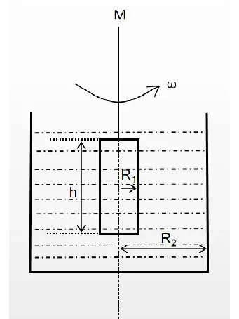
A synchronous motor drives the spindle (cylinder, disc, or cone) immersed in the fluid. Due to fluid viscosity, rotational resistance causes a lag that deflects an internal calibrated hairspring. The resulting torque is measured electronically and converted into accurate dynamic viscosity values.
- Ensure the displayed torque percentage scale is maintained between 20% and 90% (or 10% to 90% according to specific instrument specifications) to guarantee optimal accuracy.
- If the percentage exceeds 90%, decrease the rotational speed or switch to a smaller spindle.
- If the percentage is below 10% – 20%, increase the rotational speed or switch to a larger spindle.
- Strictly align the fluid level with the engraved immersion mark on the spindle shaft. For small sample adapters, use the precise sample volume specified in the manual.
- Air bubbles trapped beneath the spindle surface introduce significant frictional errors. Slowly immerse the spindle at a tilted angle into the liquid to allow trapped air to escape freely.
 |
- Thoroughly clean the spindle and sample chamber immediately after every measurement, especially when testing resins, paints, inks, and adhesives.
- Soak in compatible organic solvents and gently wipe with non-abrasive cloths. Never use metal scrapers or sharp tools, as surface scratches disrupt laminar fluid flow and compromise calibration accuracy.
Explore our complete range of digital viscometers: HINOTEK Viscometer Category.
For more foundational knowledge on viscosity testing, read our comprehensive overview: What Is A Viscometer.