
1. Introduction
The light-source lamps in a UV-Vis spectrophotometer, typically a tungsten lamp and a deuterium lamp, require replacement over the instrument’s service life. This work is often carried out by the manufacturer’s service engineers. Users who are trained and authorized to perform it can reduce downtime and maintenance costs by understanding both lamp replacement and optical alignment.
Replacing a spectrophotometer lamp is not simply a matter of fitting a new bulb and checking that it lights up. A lamp can illuminate normally while its beam is still poorly aligned with the instrument’s optical system. This article uses the Hitachi U-3010 spectrophotometer to explain the alignment principles and the adjustment procedure described in the source article.
Service safety: Lamp compartments can contain hot components, hazardous voltages, and UV radiation. Switch off and disconnect the instrument and allow the lamp to cool before replacement or mechanical access. Energized alignment must be performed only by qualified personnel using the manufacturer’s service procedure and protective measures. Do not bypass safety interlocks. The settings below are specific to the U-3010 example.
2. Construction of the Lamp Compartment
Basic Instruments
Some basic spectrophotometers use a single tungsten lamp over their intended wavelength range. Tungsten output is weak in the ultraviolet region, so measurements in that region can have a low signal level and greater noise. Dedicated ultraviolet instruments, such as some liquid-chromatography detectors and nucleic-acid/protein analyzers, may instead use a deuterium lamp.
Dual-Lamp Instruments
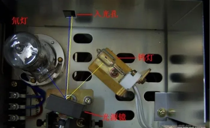
Many UV-Vis spectrophotometers use two complementary light sources to provide a useful signal-to-noise ratio over a broad range, such as 190–1100 nm: a deuterium lamp for the ultraviolet region and a tungsten lamp for the visible region. In the U-3010 example, a rotating light-source mirror selects the lamp.
In Figure 1, the deuterium lamp is on the left, the tungsten lamp is on the right, the aperture leading toward the monochromator is at the top, and the light-source switching mirror is at the bottom.
 |
3. Why Is Adjustment Necessary After Lamp Replacement?
Baseline noise and signal-to-noise ratio (S/N) are important indicators of spectrophotometer performance. They are related but are not the same quantity. Proper lamp alignment helps maximize the useful optical signal and improve measurement stability.
The aim is to align the actual light beam with the instrument’s designed optical axis. In practical terms, the brightest part of the lamp image should fall at the center of the monochromator’s entrance slit.
Lamp holders are often fixed, and small differences between individual lamps can change the position of the emitted beam in three dimensions. After replacement, the strongest part of the beam may therefore no longer be centered on the slit. In the arrangement described here, this is corrected by adjusting the reflecting angle of the light-source mirror.
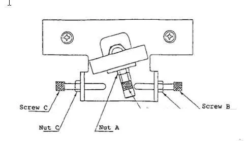 |
Adjustment Screws and Locknuts
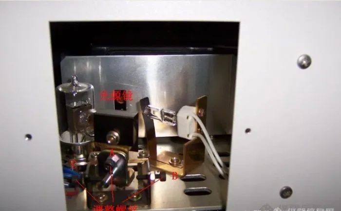
- Screws A, B, and C: Three hex-socket adjustment screws.
- Locknuts: Loosen the relevant locknut before adjustment and tighten it again after alignment.
- Screw A: Adjusts the vertical beam position for both the deuterium and tungsten lamps.
- Screw B: Adjusts the horizontal beam position for the deuterium lamp.
- Screw C: Adjusts the horizontal beam position for the tungsten lamp.
4. Adjusting the Light-Source Mirror
Preparation
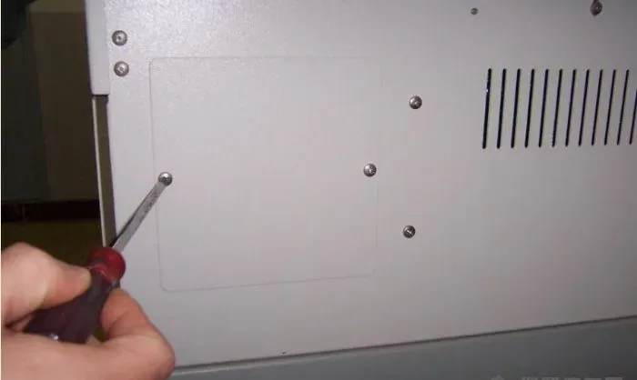
Ensure that the sample compartment contains no samples. Temporarily remove accessories such as an integrating sphere or a reflectance attachment. Following the manufacturer’s service instructions and the precautions above, remove the lamp compartment’s rear and upper covers to access the lamp and light-source mirror.
 |
 |
Adjustment After Replacing the Deuterium Lamp: U-3010
The source article specifies the following instrument settings:
| Parameter | Setting |
|---|---|
| Measurement mode | E(S) or E(R), the single-beam energy-monitoring mode |
| Light source | D2 lamp only |
| Detector high voltage | Fixed mode, approximately 300 V |
| Wavelength | 656.1 nm, a characteristic deuterium emission line |
| Adjustment screws | A and B |
Carefully adjust screws A and B to maximize the energy reading shown in the upper-right corner of the instrument display. The voltage above is an instrument setting, not an instruction to access or adjust an exposed high-voltage circuit.
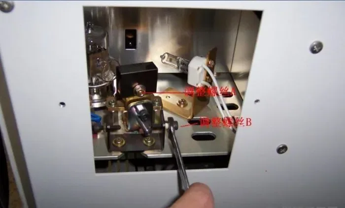 |
Although a deuterium lamp is primarily used as a UV source, it also has a characteristic emission line near 656.1 nm. Optimizing the beam position maximizes the detected intensity of this line, providing a useful indication of alignment.
Use the correct measurement mode: For this deuterium-lamp procedure, select the single-beam or energy-monitoring mode, not transmittance or absorbance mode. The method relies on monitoring the line’s energy signal.
Adjustment After Replacing the Tungsten Lamp: U-3010
The source article specifies a different set of settings for the tungsten lamp:
| Parameter | Setting |
|---|---|
| Measurement mode | T% (transmittance) |
| Light source | WI lamp only |
| Detector high voltage | Automatic mode |
| Wavelength | 600 nm |
| Adjustment screws | A and C |
Carefully adjust screws A and C to maximize the transmittance reading shown in the upper-right corner of the display, as described for the U-3010 in the source article.
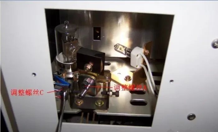 |
5. Final Checks and Precautions
- Check both lamps when adjusting screw A. This screw changes the vertical alignment of both beams. The source gives priority to the deuterium-lamp signal and describes its energy as approximately one-fifth of the tungsten-lamp energy in the example. This ratio should not be treated as a universal lamp specification.
- Verify both light sources even if only one lamp was replaced. A shared adjustment can affect the other lamp’s alignment.
- Test baseline flatness and noise after adjustment. Restore and secure the instrument covers as required, then perform the manufacturer’s prescribed performance checks to verify the result.
- Use the procedure for the actual model. Lamp-compartment layouts, adjustment mechanisms, measurement modes, and detector settings vary between instruments. The U-3010 example illustrates the alignment principle; it does not replace another model’s service manual.
- For a deep dive into the technology of Spectrophotometer: Read What Is a Spectrophotometer? The Ultimate Guide.