|
|

Introduction: Measuring the Energy Within
An oxygen bomb calorimeter (View HINOTEK Oxygen Bomb Calorimeter) is a laboratory instrument designed to measure the heat of combustion, or calorific value, of a substance. It achieves this by burning a sample in a controlled, high-pressure oxygen environment and measuring the resulting temperature change. The instrument’s primary function is to determine the total chemical energy, often called gross energy, contained within a combustible solid or liquid sample. The results are typically expressed in units like joules per gram (J/g) or kilojoules per kilogram (kJ/kg).
This measurement is critical for quality control, energy assessment, nutritional analysis, and safety evaluation across a wide range of industries, from fuel production to food science. It provides foundational data for research, product development, and regulatory compliance.
The term “bomb” is not metaphorical; it reflects the instrument’s core function and the inherent safety considerations. The sealed pressure vessel must contain a miniature, controlled explosion—a rapid combustion reaction under intense pressure. This reality directly influences the instrument’s design, the materials used in its construction, and the strict operational protocols required. For laboratory managers and procurement specialists, this connection between the instrument’s name and its function underscores the importance of build quality, material certifications, and integrated safety mechanisms like pressure release valves. These are not secondary features but fundamental design principles rooted in the physics of the measurement itself.
The Core Principle: Combustion at Constant Volume
The process of measuring calorific value in a bomb calorimeter is a direct application of thermodynamics. Here is how it works:
- A precisely weighed sample is placed inside a sealed, high-strength vessel known as the bomb.
- The bomb is filled with pure, high-pressure oxygen, typically at 25-30 atmospheres (atm), to ensure the sample burns completely.
- The sealed bomb is submerged in a known quantity of water within an insulated container called the calorimeter bucket.
- The sample is ignited electrically using a fuse wire.
- The heat released from the combustion reaction is transferred through the bomb’s walls to the surrounding water, causing the water’s temperature to rise.
- By measuring this precise temperature change (ΔT), and knowing the total heat capacity of the entire calorimeter system (Ccal), the total heat released during combustion (q) can be calculated.
A critical distinction of this instrument is that the entire process occurs at a constant volume, a condition known as isochoric. Because the volume of the sealed bomb does not change, no pressure-volume (PV) work is done by the system. This means the measured heat (qv) is equal to the change in the sample’s internal energy (ΔU), not its enthalpy (ΔH). For many applications, the difference is small, but for precise scientific work, the enthalpy can be calculated from the internal energy using the ideal gas law.
The choice of a constant-volume system is a deliberate engineering decision made to simplify the measurement and isolate the desired variable: the heat of combustion. Many chemical reactions in an open laboratory setting occur at constant pressure, where the measured heat equals enthalpy. However, attempting to contain a rapid combustion reaction while simultaneously measuring gas expansion (work) would be mechanically complex and highly prone to error. By fixing the volume, the instrument’s design eliminates the “work” variable entirely. This simplifies the core measurement to a single, highly accurate temperature reading, ensuring the instrument delivers reliable, straightforward, and repeatable data.
Anatomy of an Oxygen Bomb Calorimeter: A Component-by-Component Breakdown
Each part of an oxygen bomb calorimeter is engineered for safety, precision, and thermal efficiency. Understanding the function of each component is key to appreciating its operation.
The Bomb Vessel
|
|
|
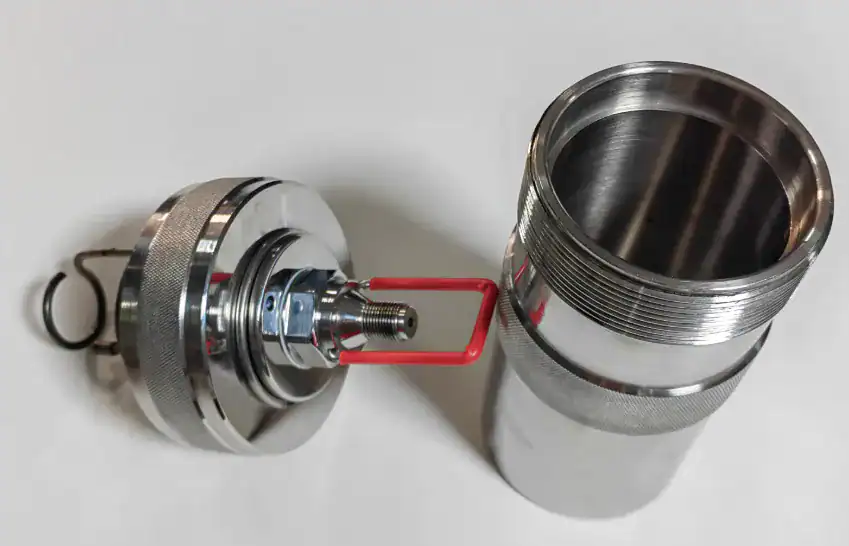
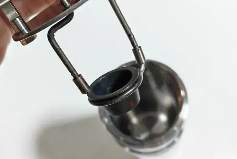
The bomb vessel is the heart of the system. It is a high-pressure container designed to safely contain the combustion reaction. It is typically machined from high-strength stainless steel or other corrosion-resistant alloys capable of withstanding internal pressures that can reach 1500 psig and the corrosive acids (such as nitric and sulfuric acid) that form during combustion. Key features include a heavy-duty screw cap or collar for sealing, a rubber gasket or O-ring to ensure a gas-tight seal, an oxygen inlet valve for charging the bomb, a gas release valve for depressurizing after a test, and two electrodes that carry the ignition current to the sample. Inside the bomb, a small, non-reactive crucible holds the sample.
The Calorimeter Bucket
The calorimeter bucket is a container that holds a precisely measured quantity of water, inside which the bomb is completely submerged. It is commonly made of metal with a highly polished outer surface to minimize the absorption and emission of radiant heat. The water in the bucket serves as the primary heat sink, absorbing the energy released from the bomb. The temperature change of this water is the primary data point for the experiment.
The Insulating Jacket (Dewar)
The insulating jacket is an outer container that surrounds the calorimeter bucket. It acts as a thermal shield, controlling heat exchange between the bucket and the laboratory environment. The design is similar to a Dewar flask. The space between the jacket and the bucket can be a simple air gap, which acts as an insulator, or it can be filled with water for active temperature control, depending on the calorimeter’s operating mode.
The Stirrer
A motorized stirrer is essential for ensuring the temperature of the water in the bucket is uniform. It continuously circulates the water, preventing the formation of localized “hot spots” near the bomb and guaranteeing that the temperature reading from the sensor is representative of the entire system. Without effective stirring, the accuracy of the measurement would be compromised.
The Ignition System
The ignition system provides the electrical energy needed to initiate combustion. It consists of an external ignition unit (a power source), the two electrodes integrated into the bomb head, and a length of combustible fuse wire, often made of nichrome. The fuse wire is stretched between the electrodes and carefully positioned so that it is in direct contact with the sample. When the ignition unit is activated, a current passes through the wire, causing it to heat up and ignite the sample.
The Temperature Sensor
This is a high-precision device used to measure the temperature of the water in the bucket. Modern calorimeters use high-resolution sensors like Platinum Resistance Thermometers (PRTs) or thermistors. These sensors are capable of detecting temperature changes with an accuracy of 0.001°C or better, a level of precision required by most international standard test methods.
| No. | Name | Unit | Quantity |
| 1 | XYR-1A+ Main unit (including single chip, oxygen bomb, water jacket, water bucket, stirrer) | set | 1 |
| 2 | Oxygen bomb head holder | set | 1 |
| 3 | Oxygen bomb seat | set | 1 |
| 4 | Temperature sensor | piece | 1 |
| 5 | Thermometer(0-50ºC) | piece | 1 |
| 6 | Stopper for thermometer (silica gel stopper 2 #) | piece | 1 |
| 7 | Ignition wire (Ф0.1 Nickel-Chromium wire) | meter | 10 |
| 8 | Crucible | piece | 2 |
| 9 | Discharging valve | piece | 1 |
| 10 | Oxygen decompression device | piece | 1 |
| 11 | Oxygen pipe | pair | 1 |
| 12 | O type seal ring(φ20×2.4mm) | piece | 5 |
| 13 | O type seal ring(φ8×1.9mm) | piece | 5 |
| 14 | O type seal ring(φ6×1.9mm) | piece | 5 |
| 15 | Airproof ring (largest O type) | piece | 2 |
| 16 | Benzoic acid | piece | 10 |
| 17 | Water aspirator | piece | 1 |
| 18 | Printing paper | roll | 1 |
| 19 | Stopping ring for thermometer (1#) | piece | 4 |
| 20 | Silicon stopper (7#) | piece | 1 |
Please note that benzoic acid is in powder form and the thermometer contains liquid, so these two accessories cannot be shipped by air.
Operating Modes: Isoperibol vs. Adiabatic Systems
No insulation is perfect, so there will always be some amount of heat exchange between the calorimeter bucket and the lab environment. The operating mode of the calorimeter defines how the instrument manages and corrects for this unavoidable heat leak.
Isoperibol Method
In an isoperibol system, the temperature of the outer insulating jacket is kept constant throughout the experiment. As the sample burns, the temperature of the inner bucket rises, while the jacket temperature stays the same. This creates a temperature differential between the bucket and the jacket, causing a predictable and measurable rate of heat leak. The calorimeter’s microprocessor continuously monitors the temperatures of both the bucket and the jacket. It then applies a mathematical correction, often based on the Regnault-Pfaundler formula, to the final temperature reading to perfectly account for the heat that was gained from or lost to the jacket.
Adiabatic Method
In an adiabatic system, the goal is to eliminate heat transfer altogether. To achieve this, the temperature of the outer jacket is actively and continuously adjusted to perfectly match the temperature of the inner bucket at all times. This is accomplished using a system of heaters and coolers that respond in real-time to the bucket’s temperature rise. By maintaining a zero temperature differential between the bucket and the jacket, the heat leak is effectively prevented. Because no heat is transferred, the calculation of the final result is simpler, as no correction for heat leak is needed.
Other Modern Methods
- Static Jacket: This is a simpler, uncontrolled system where the jacket is not actively temperature-controlled. The rate of heat leak is measured during a pre-period before ignition and is assumed to remain constant throughout the test. This is a less precise but more affordable approach.
- “Dry” or Aneroid Systems: These innovative designs eliminate the water bucket entirely. The bomb itself is surrounded by a precisely machined aluminum sleeve, and the temperature rise of the vessel is measured directly. This method removes the need to handle water and allows for much faster analysis times.
The evolution from adiabatic to microprocessor-controlled isoperibol systems reflects a major trend in laboratory instrumentation: the shift from achieving precision through mechanical complexity to achieving it through computational power. Historically, the adiabatic method was dominant because it solved the heat leak problem mechanically—by attempting to build a “perfectly insulated” box. This was the most practical solution before the advent of advanced electronics. The isoperibol method, while known, was considered less convenient due to the difficult manual calculations required to correct for the heat leak.
The introduction of microprocessors completely changed this dynamic. A computer can perform the heat leak correction calculations instantly and with greater accuracy than a human ever could. This technological shift made the mechanically simpler isoperibol system not only more practical but also faster and more efficient. The engineering challenge shifted from “how to prevent heat leak” to “how to perfectly measure and correct for it.” For today’s laboratories, this means a modern isoperibol calorimeter is often faster, more reliable, and requires less maintenance than a more complex adiabatic model, making it a better investment for most high-throughput applications.
The following table provides a clear comparison of the two primary operating modes, translating their technical specifications into practical consequences for lab operations.
| Feature | Isoperibol Method | Adiabatic Method |
| Jacket Temperature Control | Maintained at a constant temperature. | Actively adjusted to match the bucket temperature. |
| Heat Exchange | A predictable heat leak occurs, which is measured and corrected for. | Heat leak is virtually eliminated (adiabatic = no heat transfer). |
| Calculation Complexity | Requires a mathematical correction for heat leak (automated by modern controllers). | Simpler calculation; no heat leak correction needed. |
| System Complexity | Mechanically simpler jacket and control system. | More complex system with heaters/coolers for active jacket control. |
| Typical Throughput | Generally faster; allows for higher sample throughput (up to 8 tests/hour). | Generally slower due to the time needed for jacket temperature to stabilize. |
| Primary Advantage | Speed, high throughput, and lower energy/utility requirements. | High precision with simplified final calculations (historically the standard). |
A Practical Guide: Running a Test from Start to Finish
Following a standardized procedure is essential for obtaining accurate and repeatable results with an oxygen bomb calorimeter.
Step 1: Sample Preparation
- Weighing: Using an analytical balance, accurately weigh the sample (typically 0.5–1.0 g) to the nearest 0.1 mg. The sample mass is a critical variable in the final calculation.
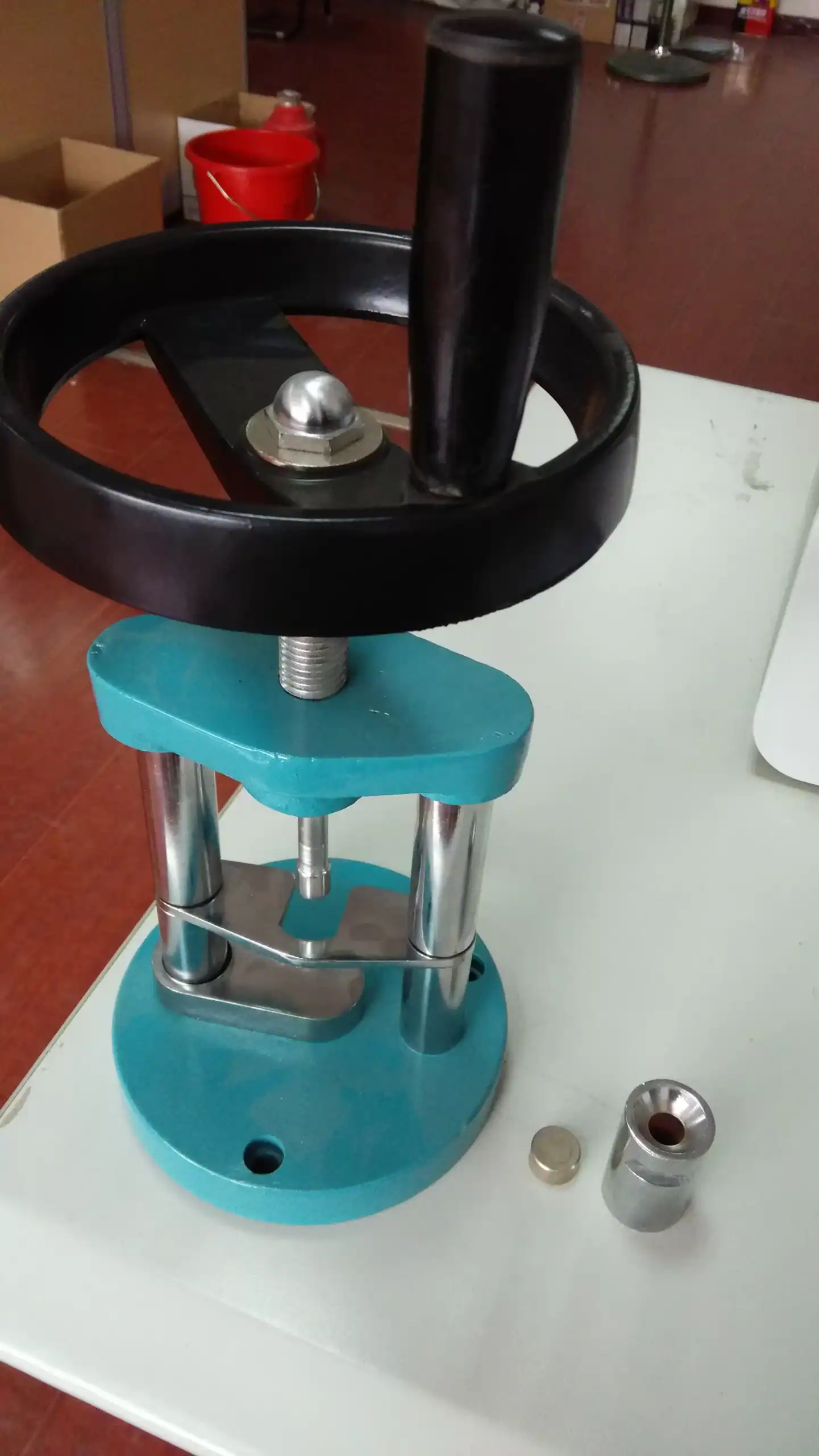
- Pelletizing Solids: For solid, powdered samples like coal, food, or biomass, use a pellet press to form a compact pellet. This ensures the sample does not get blown out of the crucible during oxygen filling and helps promote uniform combustion.

Pelletizing Solids For solid samples, we must use a pellet press to compress the sample into a disc shape. Based on our experience, powdered or fragmented samples can be dispersed by gas flow and may even explode instantly during use.
- Handling Liquids: Non-volatile liquids can be weighed directly into the sample crucible. Volatile liquids, such as gasoline or aviation fuel, must be handled carefully to prevent evaporation before ignition. This is often done by weighing the liquid in a sealed gelatin capsule or by using a special tape to cover the crucible.
Step 2: Assembling the Bomb
- Fuse Wire: Cut a precise length (e.g., 10 cm) of fuse wire. The wire should be either weighed or its length measured accurately, as its combustion contributes to the total heat released.
- Attachment: Secure the ends of the fuse wire to the two electrodes on the bomb head. Position the wire so it makes firm contact with the sample pellet or hangs just above the surface of a liquid sample. It is critical that the wire does not touch the metal crucible, as this would cause an electrical short circuit.
- Sealing: Place the bomb head into the bomb cylinder. Some standard procedures require adding 1 mL of distilled water to the bottom of the bomb at this stage to ensure all water vapor produced during combustion fully condenses. Tightly screw on the cap or collar to create a perfect, high-pressure seal.
Step 3: Charging the Bomb with Oxygen
-
- Connect the bomb’s inlet valve to an oxygen cylinder using a filling connection.
- Slowly fill the bomb with pure oxygen to the required pressure, typically 30 bar (435 psi or ~30 atm). Do not exceed the manufacturer’s specified maximum pressure. Some procedures recommend a purge cycle—filling the bomb, releasing the pressure, and refilling—to remove any atmospheric nitrogen that was trapped inside.
Step 4: Preparing the Calorimeter
- Fill the calorimeter bucket with a precise mass of water (e.g., 2000 ± 0.5 g). The water temperature should ideally be slightly below room temperature to minimize initial heat gain from the environment.
- Carefully lower the charged and sealed bomb into the water in the bucket, making sure it is fully submerged.
- Connect the ignition leads from the calorimeter to the electrodes on the bomb head.
- Place the calorimeter lid on, ensuring the stirrer and thermometer are correctly positioned in the water and that the stirrer can rotate freely without obstruction.
Step 5: Firing the Bomb and Recording Data
- Start the stirrer motor to begin circulating the water.
- Allow the system to run for several minutes to reach thermal equilibrium. During this pre-fire period, record the initial temperature (Tinitial) at regular intervals to establish a stable baseline.
- Fire the bomb by pressing the ignition button for the specified time (e.g., 3-5 seconds).
- The water temperature will begin to rise rapidly within seconds. Record the temperature at regular intervals (e.g., every 30-60 seconds) as it rises.
- Continue recording the temperature until it reaches a stable maximum and then begins to slowly fall. Continue recording for several more minutes to establish the post-combustion cooling rate, which is needed for heat leak corrections.
Step 6: Post-Test Procedures
- Once data collection is complete, remove the bomb from the calorimeter. Slowly open the gas release valve to safely vent the high-pressure gases inside.
- Unscrew the cap and open the bomb. Inspect the interior for any signs of incomplete combustion, such as soot or unburned sample, which would invalidate the test.
- Carefully remove any unburned pieces of the fuse wire. Measure their total length or mass to determine how much of the wire was consumed during ignition.
- Wash the interior surfaces of the bomb with distilled water. This solution, known as the “bomb washings,” is collected and saved for titration to determine the amount of nitric and sulfuric acid formed during combustion.
Calibration: The Foundation of Accurate Measurement
An accurate result from a bomb calorimeter depends entirely on a proper calibration. The goal of calibration is to determine the “Energy Equivalent” of the specific instrument being used.
The “Energy Equivalent” (Ccal)
It is not possible to calculate the heat released by only considering the properties of the water. The steel bomb itself, the metal bucket, the stirrer, and the thermometer all absorb some of the heat generated by the combustion. The Energy Equivalent (also called the calorimeter constant or heat capacity of the calorimeter) is a single value that represents the total amount of energy the entire calorimeter system absorbs for every 1°C rise in temperature.
The Role of Benzoic Acid
Benzoic acid is the internationally recognized primary standard for calibrating oxygen bomb calorimeters. It is chosen as the standard for several ideal properties: it is available in high purity, it is stable, it is not hygroscopic (it does not absorb water from the air), it is not volatile, and most importantly, it has a precisely known and certified heat of combustion (approximately 26,454 J/g or 6318 cal/g).
The Calibration Process
A standard calibration run is performed in exactly the same way as a normal test, but a precisely weighed pellet of benzoic acid is used instead of an unknown sample. Because the total heat that will be released by the benzoic acid is known (Mass of benzoic acid × Heat of combustion of benzoic acid), the Energy Equivalent (Ccal) of the calorimeter can be calculated by dividing this known amount of heat by the corrected temperature rise (ΔT) observed during the test.
This calibration is not just a procedural step; it is a substitution measurement that directly links the performance of a specific, physical instrument back to a fundamental chemical standard. No two calorimeters are perfectly identical. Minor variations in the mass of the bomb, the exact placement of the stirrer, or the sensor’s response mean each setup will have a unique heat capacity. The calibration run measures the effective heat capacity of the entire system as a whole. It effectively “fingerprints” the unique thermal properties of that exact calorimeter setup. This means the accuracy of every subsequent measurement of an unknown sample is entirely dependent on the quality of this initial calibration. For this reason, calibration should be performed regularly (e.g., daily or weekly) and whenever any part of the system is changed or serviced.
Calculating the Calorific Value: From Temperature Rise to Final Result
The final calculation converts the raw temperature data into the calorific value of the sample, incorporating all necessary corrections.
The Basic Calculation
First, the total heat absorbed by the calorimeter system (qcalorimeter) is calculated using the energy equivalent determined during calibration.
The formula is:
qcalorimeter=Ccal×ΔTcorrected
where Ccal is the energy equivalent of the calorimeter, and ΔTcorrecte is the corrected temperature rise, adjusted for heat exchange (also referred to as the cooling correction).
The Principle of Conservation of Energy
According to the first law of thermodynamics, the total heat released by the combustion process (qtotal) is equal in magnitude but opposite in sign to the heat absorbed by the calorimeter (qcalorimeter), reflecting the exothermic nature of combustion.
qtotal=−qcalorimeter
Essential Corrections
The total heat released (qtotal) does not come from the sample alone. It also includes heat from side reactions that must be accounted for. To find the heat generated by the sample, these contributions must be subtracted.
The formula is: qsample=qtotal−qfuse−qacid
- Fuse Wire Correction (qfuse): The ignition wire itself burns and releases a small amount of heat. This contribution must be subtracted from the total. It is calculated by multiplying the mass (or length) of the wire that was consumed during the test by its known heat of combustion (e.g., 1400 cal/g or 2.3 cal/cm).
- Acid Correction (qacid): Under the high-pressure oxygen conditions inside the bomb, any nitrogen from the air forms nitric acid, and any sulfur present in the sample forms sulfuric acid. These are exothermic reactions that do not occur in normal atmospheric combustion, so the heat they produce must be subtracted. The amount of each acid formed is determined by titrating the bomb washings collected after the test. A standard correction factor (e.g., 1.43 calories per mL of N/10 HNO₃) is then applied.
Final Calculation of Gross Calorific Value (GCV)
The Gross Calorific Value (GCV), also known as the Higher Heating Value (HHV), is the amount of heat released during the complete combustion of a unit mass of a sample. It is calculated by dividing the corrected heat released by the sample (qsample) by the original mass of the sample (msamplem).
The formula is: GCV=qsample/msamplem
Applications: Where the Oxygen Bomb Calorimeter is Used
The oxygen bomb calorimeter is a versatile instrument used across numerous industries for quality control, research, and safety analysis.
Fuel Industry (Coal, Oil, Biofuels)
This is the most traditional and widespread application. The GCV is a primary specification for determining the quality and monetary value of fuels like coal, coke, and fuel oil. It is used to certify coal grades for power plants, test the energy content of aviation and marine fuels, and analyze refuse-derived fuels (RDF) from municipal solid waste to assess their potential as an energy source.
Food and Nutrition
The calorimeter is used to determine the metabolizable energy content (calories) of food products for nutritional labeling and research. It is essential for measuring the caloric content of specialist diets, breakfast cereals, snack foods, and animal feed. In metabolic studies, researchers use it to analyze the energy content of feces to determine how efficiently nutrients are absorbed by the body.
Waste Management and Environmental Science
This field uses calorimeters to evaluate the energy recovery potential of various waste streams. This includes analyzing the energy content of biomass like wood waste from pulp mills, agricultural residues (such as olive pits and sugarcane bagasse), seaweed, and low-quality compost to determine if they can be used as sustainable, alternative fuels.
Research and Education
The bomb calorimeter is a fundamental tool in university chemistry and engineering laboratories. It is used for teaching the principles of thermodynamics and for research in materials science, such as determining the standard enthalpies of formation for new chemical compounds or studying the energy content of polymers and composites.
Specialized and Safety Applications
The instrument is also used to characterize highly energetic materials or for safety testing. This includes measuring the energy release of propellants, pyrotechnics, and explosives for the defense and aerospace industries. In another safety application, cosmetic products like hairspray or lotions are tested to determine their flammability and explosion risk to comply with transportation regulations, particularly for air travel.
The wide range of applications shows that while the instrument itself is versatile, the methodology must be adapted to the sample’s specific nature. A solid piece of coal is simple to handle. A volatile fuel, however, requires specialized handling with gelatin capsules or sealing tape to prevent mass loss from evaporation before the test can begin. Ammunition propellants generate their own oxygen during combustion, so the standard procedure of filling the bomb with excess oxygen must be modified, often by using an inert gas like nitrogen instead. This shows a clear relationship: the properties of the sample dictate the required procedure to obtain a valid result. For a supplier like HINOTEK, this means that providing application-specific notes, specialized accessories like pellet presses or capsules for liquids, and expert support on these varied methodologies is a significant value-add that addresses a customer’s entire analytical problem, not just their need for a piece of hardware.
How to Select an Oxygen Bomb Calorimeter for Your Lab
For lab managers, procurement specialists, and researchers, selecting the right instrument involves matching its features to the lab’s specific needs, workflow, and budget.
1. Sample Throughput (Tests per Day)
The first question to ask is: how many samples do you need to analyze daily?
- Low Throughput (2-4 tests/hour): For teaching labs or research applications with a small number of samples, a manual or plain jacket calorimeter may be sufficient and more cost-effective.
- High Throughput (6-8+ tests/hour): For a production or quality control lab, an automated isoperibol or “dry” system is necessary. These systems, often equipped with multiple bomb vessels, can operate almost continuously to keep up with high demand.
2. Level of Automation and Ease of Use
How much operator time can be dedicated to running tests?
- Manual: The operator performs all steps: weighing the sample, assembling the bomb, filling the water bucket, and charging the bomb with oxygen. This is the lowest cost option but requires the most operator involvement.
- Semi-Automatic: Key steps like filling the water bucket are automated, but the operator still manually fills the bomb with oxygen. This offers a good balance of cost and efficiency.
- Fully Automatic: The entire process, from oxygen filling to rinsing the bomb after the test, is automated. This is the highest cost option but offers “walk-away” operation, maximizing operator efficiency and enhancing safety, especially when handling hazardous samples like explosives.
3. Required Precision and Accuracy
What are the requirements of your standard test method (e.g., ASTM, ISO) or research protocol? Isoperibol and adiabatic systems generally offer the highest precision. The quality of the temperature sensors and the sophistication of the controller’s correction algorithms are key factors that determine the instrument’s ultimate accuracy.
4. Sample Type and Versatility
What kinds of materials will you be testing?
- Corrosive Samples: If testing materials with high sulfur or halogen content, a bomb constructed from a more resistant alloy (like Hastelloy) may be required to prevent corrosion.
- Volatile Liquids: The system should be compatible with accessories like sealed capsules to handle volatile samples without evaporation.
- Low Energy Samples: For samples that release very little heat, a semi-micro calorimeter with higher sensitivity may be needed to obtain a measurable temperature rise.
5. Safety Features
What are the inherent risks associated with your samples and lab environment? Non-negotiable safety features include robust bomb construction with proof of pressure testing, reliable pressure release mechanisms, and secure electrical connections. Fully automated systems can also enhance safety by minimizing operator handling of the high-pressure vessel.
6. Budget and Total Cost of Ownership
The initial purchase price can range from around $10,000 for basic manual models to over $50,000 for fully automated, high-throughput systems. However, it is also important to consider the total cost of ownership. This includes operational costs for consumables (fuse wire, certified benzoic acid), potential replacement parts (bomb vessels can wear out over time and cost $500-$1,000 to replace), and utilities.
Conclusion: A Vital Tool for Precise Energy Measurement
The oxygen bomb calorimeter remains the definitive instrument for accurately measuring the heat of combustion. Its fundamental principle of constant-volume combustion, combined with modern electronics, sophisticated software, and automation, provides reliable and repeatable data that is essential for science and industry.
From ensuring the quality of the fuel that powers global commerce to verifying the nutritional labels on our food, the precise energy measurements provided by the oxygen bomb calorimeter are a cornerstone of quality control, safety, and innovation. Understanding its principles, components, and proper operation is key to unlocking its full potential in the laboratory.
If you are ready to find the right Oxygen Bomb Calorimeter for your laboratory, please browse our complete product range: Oxygen Bomb Calorimeter
This guide is maintained by HINOTEK’s core technical team, comprised of senior engineers and application scientists with over two decades of hands-on experience in fields such as microscopy, centrifugation, and spectrophotometry. We are committed to ensuring that every piece of information in this guide—from instrument principles and technical specifications to laboratory procurement advice—maintains the highest level of accuracy and timeliness.
This content is regularly reviewed and updated to reflect the latest industry standards and technological advancements. We value feedback from the global scientific community. Should you have any questions or suggestions, or wish to discuss any technical details, please do not hesitate to contact our expert team at [email protected].