Guide Navigation
- 1. Introduction: The Heart of the High-Temperature Laboratory
- 2. The Science of Controlled Heat: How a Muffle Furnace Works
- 3. Anatomy of a Muffle Furnace: A Component-by-Component Breakdown
- 4. A Tool of a Thousand Uses: Key Applications of the Muffle Furnace
- 5. From Theory to Practice: Step-by-Step Procedural Guides
- 6. Best Practices for Safe Operation and Maintenance
- 7. Conclusion: The Enduring Importance of the Muffle Furnace
1. Introduction: The Heart of the High-Temperature Laboratory
|
|

1.1 What is a Muffle Furnace? A Foundational Definition
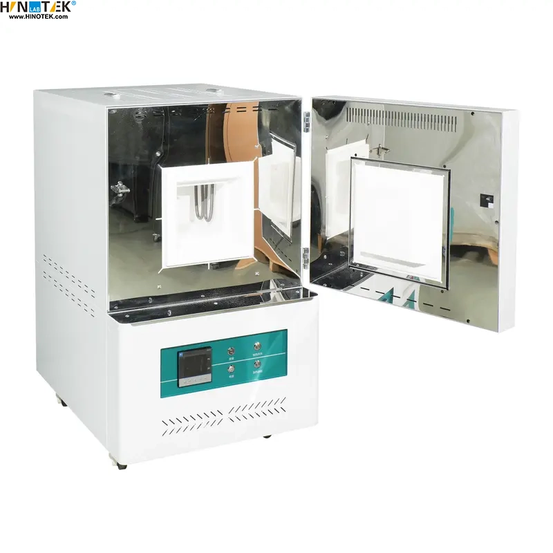
A Muffle Furnace (View HINOTEK Muffle Furnace Category) is a high-temperature, front-loading box-type oven used extensively in laboratories and industrial settings to heat materials within a precisely controlled and contamination-free environment. It stands as a vital piece of equipment for a wide range of thermal processing applications, most notably for analyzing the non-combustible and non-volatile content of a sample—a procedure known as ashing.
The name itself provides a clue to its fundamental design. The term “muffle” refers to the furnace’s inner chamber, which is constructed from a high-temperature refractory material. This chamber serves to isolate, or “muffle,” the sample from the direct heat source and any potential atmospheric contaminants, ensuring the integrity of the process. This design guarantees that the material is heated uniformly and cleanly, which is critical for achieving accurate and repeatable results in scientific research and quality control.
1.2 From Forge to Lab: A Brief History and Evolution
The concept of the muffle furnace predates modern electrical laboratories. Early furnaces were fuel-fired, relying on the combustion of oil or gas to generate heat. In this context, the muffle was an absolute necessity. It formed a physical barrier that protected the sample from the direct flame and its byproducts, such as ash, soot, and reactive gases, which would otherwise contaminate the material being processed.
The widespread adoption of electricity marked a pivotal moment in the furnace’s evolution. The development of high-temperature electric heating elements eliminated the problem of fuel-based contamination entirely. However, the muffle design was not abandoned; instead, its purpose was elegantly repurposed for a new set of advanced requirements. While the original problem of fuel contamination was solved, a new challenge emerged in high-purity analysis: preventing contamination from the heating elements themselves (which can shed particles at high temperatures) and ensuring that every part of a sample reaches the exact same temperature. The isolated chamber design proved to be the perfect solution. It physically separates the sample from the elements and creates an ideal environment for uniform heat transfer through radiation and convection.
This technological shift explains why the name and design persist. Today, the terms “muffle furnace,” “chamber furnace,” and “box furnace” are often used interchangeably to describe these modern, front-loading, electrically heated devices that are staples in laboratories worldwide.
1.3 Why Use a Muffle Furnace? The Core Advantage of Indirect Heating
The defining characteristic and primary advantage of a muffle furnace lie in its principle of indirect heating. The sample placed inside the chamber is heated without ever coming into direct contact with the heating elements. This fundamental separation is the source of two critical benefits that make the muffle furnace indispensable for precision work.
First, it creates a contamination-free environment. In sensitive analytical processes like determining the ash content of a food product or preparing a sample for trace metal analysis, even minuscule contamination can skew results. The muffle chamber ensures that the only thing affecting the sample is controlled heat, preserving its chemical purity.
Second, it facilitates highly uniform heating. Heat is transferred to the sample gently and evenly from all sides via radiation from the hot chamber walls and convection of the air or gas inside. This eliminates “hot spots” that could occur with direct heating, ensuring that the entire sample undergoes the same thermal process. This uniformity is vital for consistent material transformations, such as annealing metals or sintering ceramics, where precise temperature control dictates the final properties of the material.
1.4 Muffle Furnace vs. Tube Furnace: Choosing the Right Tool
For newcomers to high-temperature lab equipment, a common point of confusion is the distinction between a muffle furnace and a tube furnace. While both are used for thermal processing, their design and ideal applications differ significantly. A muffle furnace features a box-shaped chamber, making it perfect for processing multiple samples at once, larger samples, or applications conducted in a standard air atmosphere. In contrast, a tube furnace utilizes a narrow, cylindrical chamber, which is better suited for processing smaller or single samples in a highly controlled or specialized atmosphere, such as a vacuum or a specific flowing gas (e.g., nitrogen, argon). Making the right choice depends entirely on the specific requirements of the experiment or process.
Table 1: Muffle Furnace vs. Tube Furnace at a Glance
|
|
|

| Feature | Muffle Furnace | Tube Furnace |
| Chamber Shape | Rectangular (Box) | Cylindrical (Tube) |
| Sample Capacity | High; suitable for multiple crucibles, larger parts | Low; typically for a single boat or smaller samples |
| Atmosphere Control | Standard air atmosphere; some models allow for modified atmosphere with gas ports | Excellent; ideal for high vacuum or precisely controlled flowing gas environments |
| Temperature Uniformity | Very good throughout the chamber volume | Excellent along the central heated zone of the tube |
| Cost | Generally more affordable for a given volume | More expensive, especially models with high-vacuum capabilities |
| Typical Use Cases | Ashing, loss on ignition, annealing, sintering in air, glass fusing, enameling | Processing in inert/reducing atmospheres, chemical vapor deposition (CVD), single-crystal growth, material synthesis under vacuum |
2. The Science of Controlled Heat: How a Muffle Furnace Works
2.1 The Core Principle: Indirect Heat Transfer
 |
 |
The operation of a modern electric muffle furnace is governed by the principles of indirect heat transfer and precise thermal regulation. The heating elements, which are the source of the thermal energy, are strategically placed within the furnace walls, outside the sealed inner muffle chamber. When energized, these elements do not heat the sample directly. Instead, they transfer energy to the chamber and its contents through two primary physical mechanisms:
- Thermal Radiation: As the heating elements reach high temperatures, they emit a significant amount of energy in the form of infrared radiation. This electromagnetic energy travels through the space inside the furnace and is absorbed by the inner walls of the muffle chamber and by the surface of the sample itself. The hot chamber walls then re-radiate this energy, creating a uniform field of heat that envelops the sample.
- Thermal Convection: The air or other gases inside the sealed muffle chamber are heated by the radiating elements and hot chamber walls. This heating causes the gas to expand and its density to decrease, creating natural convection currents. The circulating gas efficiently transfers heat to all surfaces of the sample, including those not in the direct line of sight of the heating elements, further enhancing temperature uniformity.
2.2 A Step-by-Step Operational Cycle
A typical heating process in a muffle furnace is a carefully orchestrated sequence, managed by its electronic control system to ensure accuracy and repeatability.
- Programming: The cycle begins at the control panel. The user inputs the desired thermal profile, which includes the target temperature (setpoint), the ramp rate (the speed of temperature increase in degrees per minute), and the soak or dwell time (the duration for which the target temperature is maintained).
- Heating Phase: Once the program starts, the controller sends electricity to the high-resistance heating elements. According to the principle of Joule heating, the resistance of the elements causes the electrical energy to be converted into thermal energy, and they begin to heat up rapidly.
- Heat Transfer and Insulation: The elements radiate heat into the muffle chamber. The layers of high-quality insulation surrounding the chamber are critical at this stage; they minimize heat loss to the external environment, allowing the furnace to reach and maintain very high temperatures efficiently and with lower energy consumption.
- Temperature Regulation: This is where the furnace’s precision originates. A thermocouple sensor, positioned inside the chamber, continuously measures the actual temperature and sends this information back to the temperature controller. This controller is not a simple on/off thermostat, which would lead to wide temperature fluctuations. Instead, it is almost always a sophisticated PID (Proportional-Integral-Derivative) controller. The PID algorithm makes constant, nuanced adjustments to the power supplied to the heating elements. The Proportional component responds to the current difference between the setpoint and the actual temperature. The Integral component corrects for any small, persistent errors over time, ensuring the furnace doesn’t settle slightly below the target. The Derivative component anticipates future temperature changes by analyzing the rate of change, preventing the furnace from overshooting the setpoint. This intelligent feedback loop allows the furnace to maintain the target temperature with remarkable stability, often within 1%.
- Soaking Phase: The furnace holds the target temperature for the pre-programmed duration. During this phase, the intended thermal process—be it the complete combustion of organic matter in ashing, the recrystallization of grains in annealing, or the fusion of particles in sintering—is allowed to reach completion.
- Cooling Phase: After the soak time elapses, the controller cuts power to the heating elements. The furnace then begins to cool down. Depending on the application’s needs, this can be a passive process (letting the furnace cool naturally over many hours) or a controlled ramp-down, where the controller manages the cooling rate to prevent thermal shock to the sample.
This ability to execute a precise, pre-programmed temperature-time profile is what elevates the muffle furnace from a simple oven to an indispensable scientific instrument. The reliability of experimental results is directly tied to the sophistication of its control system.
3. Anatomy of a Muffle Furnace: A Component-by-Component Breakdown
A laboratory muffle furnace is a system of carefully engineered components working in concert to deliver controlled, high-temperature environments safely and efficiently. Understanding its anatomy is key to selecting the right model and operating it effectively.
3.1 The Heating Core: Elements and Capabilities
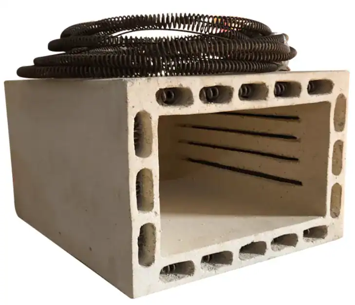
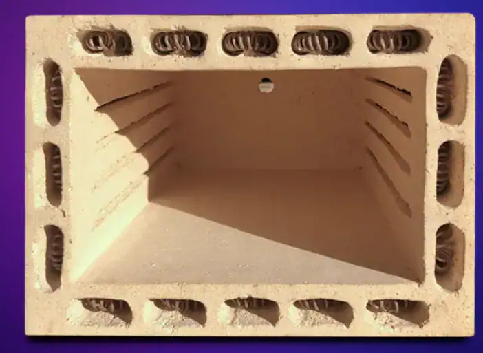
The heating elements are the heart of the furnace, as their material composition directly determines the unit’s maximum operating temperature and its suitability for different applications.
|
|
|
|
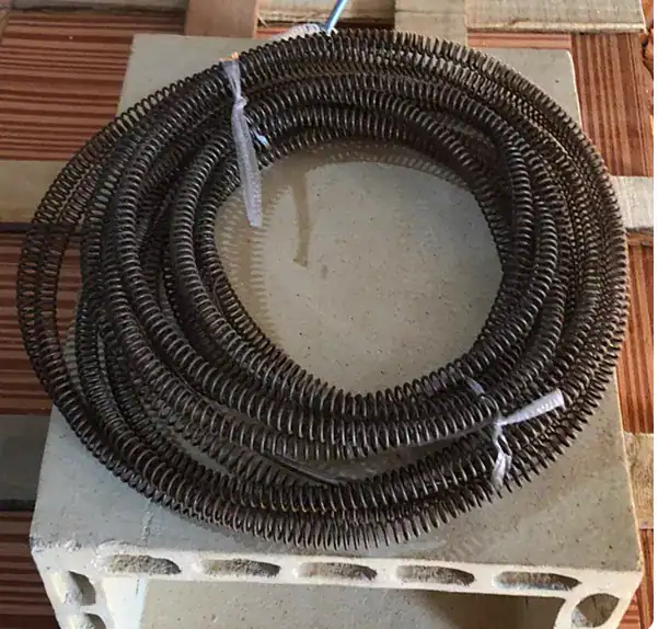
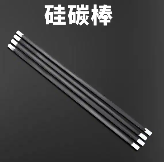

Table 2: Muffle Furnace Heating Elements: Materials and Performance
| Element Material | Common Names / Composition | Max. Temperature (∘C) | Key Characteristics | Common Applications |
| Metallic Wire | Kanthal (FeCrAl alloy), Nichrome (NiCr) | 1000–1200 | Most common, cost-effective, robust, and durable for general laboratory use. | General lab heating, ashing of organic samples, annealing of non-ferrous metals, tempering. |
| Silicon Carbide (SiC) | Silicon Carbide | Up to 1600 | Excellent for higher temperature ranges, provides rapid heating, but can be more brittle than metallic elements. | Sintering of ceramics, glass melting and fusing, heat treatment of some steels and alloys. |
| Molybdenum Disilicide (MoSi2) | Molybdenum Disilicide | Up to 1800 (some models to 1900) | Achieves the highest temperatures, long-lasting at high temps, but requires careful operation to prevent thermal shock. | Advanced metallurgical research, sintering of high-tech ceramics (e.g., zirconia), ultra-high temperature material testing. |
3.2 The Protective Shell: Chamber and Insulation
The structure surrounding the heating elements is engineered for thermal efficiency and operator safety.
 |
-
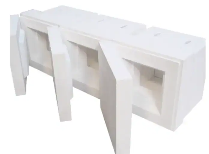
- Muffle Chamber: This is the innermost layer where the sample is placed. It is constructed from high-purity, durable refractory materials like molded alumina, quartz, or other technical ceramics. These materials are chosen for their ability to withstand extreme thermal shock, resist chemical attack from fumes, and provide a clean, particle-free environment.
-
- Insulation: The quality of insulation is paramount. Modern furnaces utilize advanced, lightweight ceramic fiber insulation (such as polycrystalline mullite or alumina fibers) for rapid heat-up and cool-down times and excellent energy efficiency. This is a significant improvement over older, heavier refractory bricks, although bricks are still used in some heavy-duty industrial applications.
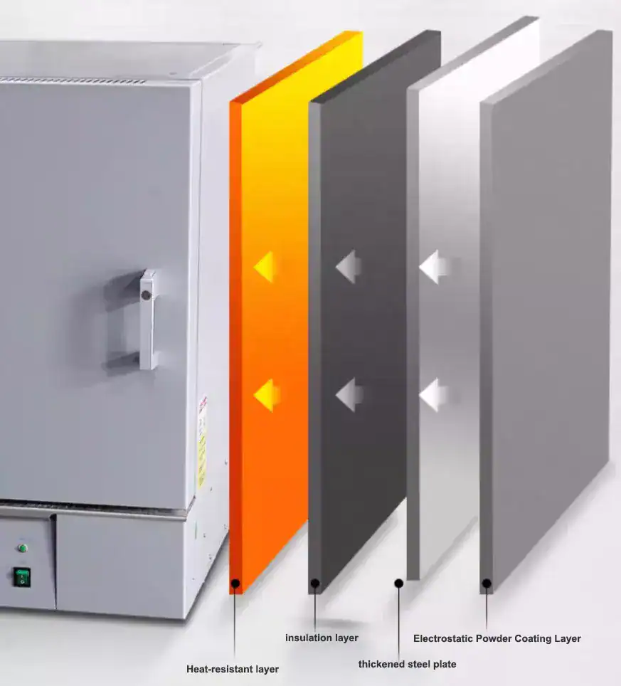 |
- Construction and Housing: High-quality laboratory furnaces feature a double-walled or even triple-walled construction. This design is a sophisticated method of managing heat flow. The space between the inner and outer walls creates an air gap, which acts as an effective thermal break, significantly reducing heat transfer to the exterior. This multi-layered approach serves three purposes: it maximizes thermal efficiency by keeping heat inside the chamber, it improves the temperature stability of the process, and, most critically, it ensures a low external “skin temperature,” keeping the outer casing safe to touch and protecting the operator from burns. The outer housing is typically fabricated from powder-coated or textured stainless steel for durability, corrosion resistance, and ease of cleaning.
3.3 The Control Center: User Interface and Electronics
The control system is the brain of the furnace, dictating the precision of the entire operation.
 |
-
- Temperature Controller: As previously discussed, this is typically a microprocessor-based PID controller, which is essential for the high degree of accuracy required in laboratory settings.
- User Interface: This can range from a simple digital display with push-button controls to a sophisticated, full-color touchscreen. Advanced interfaces allow for intuitive programming of complex, multi-step thermal profiles (multiple ramps, soaks, and cooling stages), real-time graphing of the process, and data logging capabilities for quality assurance and record-keeping.
 |
- Thermocouple: This is the furnace’s primary temperature sensor. It is a probe that extends into the chamber to provide continuous, real-time temperature readings to the controller. High-temperature furnaces typically use durable, long-life thermocouples, such as Type R or Type S, to ensure accuracy and reliability over many cycles.
3.4 Structural and Safety Features
Modern muffle furnaces are equipped with numerous features designed to ensure safe and reliable operation.
 |
- Door: The door is a heavily insulated component with robust hinges and a secure latching mechanism. A proper seal is crucial to prevent heat loss and maintain temperature stability. Some models feature a door that can be used as a convenient, heat-resistant shelf for loading and unloading crucibles.
- Safety Interlock Switch: This is a critical safety device that automatically cuts power to the heating elements the moment the furnace door is opened. This prevents user exposure to the dangerously high temperatures inside and the risk of electric shock from the live elements.
- Over-Temperature Protection: This is a secondary, independent safety circuit. If the primary controller fails and the temperature begins to rise uncontrollably, this system will shut down the furnace once a preset safety limit is exceeded, preventing damage to the furnace, the sample, and the laboratory.

- Ventilation/Exhaust Port: Most furnaces include an exhaust port, typically on the top or rear of the unit. This allows for the safe venting of moisture, fumes, and gases that are produced during processes like ashing, binder burnout in ceramics, or other chemical decompositions. This port can be left open to the lab’s ventilation system or connected directly to an exhaust duct for more hazardous fumes.

4. A Tool of a Thousand Uses: Key Applications of the Muffle Furnace
The muffle furnace is a remarkably versatile instrument, a fact that stems directly from its ability to provide precise, programmable control over two of the most fundamental variables in materials science: temperature and time. By manipulating these two parameters, a single piece of equipment can be used to induce profound changes in the physical and chemical properties of a vast range of materials. Whether the goal is to soften steel, densify a ceramic powder, or completely combust the organic matter in a food sample, the furnace can execute the specific thermal recipe required. It is not merely a “heater” but a “thermal process controller,” making it a cornerstone tool in countless fields.
4.1 Analytical Chemistry and Quality Control
- Ash Content Analysis (Gravimetric Analysis): This is arguably the most common application of a laboratory muffle furnace. The process involves heating a sample at a high temperature (typically 500-600°C) to completely burn off all organic matter, leaving behind only the inorganic residue, or “ash.” The weight of this ash is then measured to determine the total mineral content of the original sample. This is a critical quality control parameter in industries such as food science, agriculture (for soils and feeds), plastics, coal, and pharmaceuticals.
- Loss on Ignition (LOI): A closely related technique, LOI is frequently used in geology, environmental science, and civil engineering. It measures the change in mass of a sample after it has been heated to a high temperature. This weight loss typically corresponds to the volatile content of the sample, such as bound water, carbonates, and organic matter in soil, sediment, or cement.
- Chemical Analysis: Muffle furnaces are used to prepare samples for further, more complex analyses. For example, a sample might be ashed to remove the organic matrix before being dissolved for elemental analysis by techniques like atomic absorption spectroscopy (AAS) or inductively coupled plasma (ICP).
4.2 Materials Science and Metallurgy
- Heat Treatment of Metals: The furnace is essential for modifying the mechanical properties of metals and alloys.
- Annealing: This process involves heating a metal to a specific temperature and then cooling it very slowly. This relieves internal stresses, softens the metal, and increases its ductility, making it easier to machine or form.
- Hardening, Tempering, and Normalizing: These are other critical heat treatments used to achieve a desired balance of hardness, toughness, and strength in steel and other alloys.
- Sintering: This is a core process in both powder metallurgy and the manufacturing of technical ceramics. A compacted powder, known as a “green body,” is heated to a temperature below its melting point. At this temperature, the particles begin to fuse at their contact points through atomic diffusion, resulting in a dense, strong, solid part.
- Brazing and Soldering: These are processes for joining metal components by melting a filler metal into the joint. A muffle furnace can provide the controlled, high-temperature environment needed for these operations.
4.3 Ceramic and Glass Industries
- Glass Fusing and Melting: In art and industry, muffle furnaces are used to heat pieces of glass until they soften and fuse together, creating everything from decorative objects to specialized optical components.
- Enameling: This is the process of fusing a layer of powdered glass (enamel) onto a substrate, typically metal or ceramic. The furnace provides the high heat needed to melt the powder into a smooth, durable, and often colorful coating.
- Ceramic Firing: The furnace plays a key role in the production of advanced ceramics. It is used for binder burnout (removing the polymer binders used to shape the part), applying glazes, and firing the ceramic body to achieve its final, desired material properties.
4.4 Specialized and Emerging Fields
The precision of the muffle furnace has led to its adoption in a wide array of specialized fields:
- Dental Laboratories: Used for firing porcelain crowns and bridges and for sintering advanced ceramic prosthetics like zirconia restorations, which require very precise temperature control to achieve the correct strength and translucency.
- Biomedical and Pharmaceutical: Employed for sterilizing instruments, pre-treating medical samples for analysis, and in various drug testing protocols.
- Forensic Analysis: Used by forensic scientists to assist in the characterization and analysis of various types of physical evidence.
- Petrochemical Industry: Utilized for quality control tests on petroleum products, such as determining the ash content of lubricating oils.
5. From Theory to Practice: Step-by-Step Procedural Guides
While understanding the theory behind a muffle furnace is important, its true value is realized in its practical application. The following guides provide step-by-step instructions for some of the most common procedures performed in a laboratory muffle furnace.
5.1 Guide 1: Performing Ash Content Analysis in Food Products
Objective: To accurately determine the total inorganic mineral content of a food sample using the gravimetric method, a cornerstone of nutritional analysis and food quality control.
Equipment Needed: A muffle furnace, an analytical balance (readable to at least 0.1mg), high-temperature porcelain or silica crucibles, long metal tongs, and a desiccator with fresh desiccant.
- Step 1: Crucible Preparation. Place clean, empty crucibles in the muffle furnace. Heat them at the analysis temperature (e.g., 550°C) for at least one hour to burn off any residual moisture or contaminants. Using tongs, transfer the hot crucibles to a desiccator, allow them to cool completely to room temperature (this may take 30-60 minutes), and then weigh each one precisely on the analytical balance. Record this mass as Mass 1 (M1).
- Step 2: Sample Preparation. The sample must be homogeneous. For solid foods, this may require grinding or blending. Samples with high moisture content (e.g., fresh fruit) should be pre-dried in a standard oven to prevent the sample from spattering violently during the initial heating in the muffle furnace. High-fat samples (e.g., nuts) may need to be defatted using a solvent extraction method to ensure complete combustion.
- Step 3: Initial Weighing. Add approximately 2–5 grams of the prepared sample into a pre-weighed (tared) crucible. Weigh the crucible with the sample accurately on the analytical balance. Record this mass as Mass 2 (M2).
- Step 4: Ashing (Incineration). Place the sample-filled crucibles in the cool muffle furnace using tongs. Program the furnace to ramp up to the target temperature, typically between 550°C and 600°C for most food products. The required “soak” time at this temperature can vary significantly, from 3 to 18 hours, depending on the sample’s composition and size. The process is complete when the residue is a fine, white or gray ash, indicating that all carbon (organic matter) has been burned off.
- Step 5: Cooling and Final Weighing. Once the ashing is complete, turn off the furnace and allow it to cool to a safe temperature (below 250°C) before opening the door. Using tongs, carefully transfer the hot crucibles to a desiccator. It is critical to let them cool completely to room temperature inside the desiccator to prevent the hygroscopic ash from absorbing moisture from the atmosphere. Once cool, weigh the crucible containing the ash. Record this mass as Mass 3 (M3).
- Step 6: Calculation. The percentage of ash content is calculated using the following formula:
Ash Content (%)=(M2−M1)(M3−M1)×100
5.2 The Critical Interlude: Precision Weighing and Error Mitigation
The accuracy of the entire ashing analysis does not depend on the furnace alone; it is critically dependent on the precision of the three mass measurements. The furnace prepares the sample, but the analytical balance provides the raw data. Therefore, the furnace, desiccator, and balance must be treated as a single analytical system, where a procedural error in one stage invalidates the entire result. A change in room temperature, for example, can cause the balance’s internal components to expand or contract, leading to thermal drift. This means the balance’s zero point may shift between the weighing of M1 in the morning and M3 in the afternoon, introducing a systematic error that propagates through the final calculation. Understanding and mitigating sources of weighing error is paramount.
Common Sources of Weighing Error in Ash Analysis:
- Thermal Effects (Dynamic Buoyancy): Weighing a crucible that is still warm is the most frequent and significant source of error. The warm crucible heats the air around it, creating convection currents that flow upward along its sides. This airflow exerts a lifting force on the crucible and weighing pan, making the object appear lighter than it actually is. This phenomenon is known as “dynamic buoyancy”. This error leads to an artificially low M3 value and a falsely low calculated ash content.
- Hygroscopic Effects: The resulting ash is often highly hygroscopic, meaning it readily absorbs moisture from the air. If the crucible is not cooled completely within a sealed desiccator, or if it is left on the balance pan for too long in a humid environment, the ash will gain weight from absorbed water. This leads to an artificially high M3 value and an overestimated ash content.
- Balance Drift: Environmental factors, primarily temperature fluctuations in the laboratory, can cause the sensitive electronic and mechanical components of the balance to drift over the many hours of the ashing procedure. This can affect the stability of the zero point and the calibration (sensitivity) of the balance, introducing errors into any of the three measurements.
Best Practices for Accurate Weighing:
- Ensure Thermal Equilibrium: Always allow crucibles to cool completely to ambient room temperature inside a desiccator before weighing. This is the only way to eliminate errors from dynamic buoyancy.
- Use Proper Handling Tools: Never handle crucibles, samples, or calibration weights with bare hands. Oils, salts, and moisture from fingerprints add measurable mass. Always use clean tongs or forceps.
- Maintain a Stable Environment: The analytical balance must be placed on a dedicated, heavy, vibration-free table. It should be located away from drafts, HVAC vents, doorways, and direct sunlight. The room temperature should be stable, ideally varying by no more than 1%.
- Follow Calibration Protocols: The balance must be calibrated regularly using certified, traceable weights. For regulated industries like pharmaceuticals, this must adhere to standards such as USP General Chapter .
Table 3: Ashing Analysis – Common Sources of Error and Solutions
| Observed Problem | Probable Cause | Physical Effect | Solution |
| Ash % is consistently too low. | Weighing the crucible while it is still warm. | Convection currents (dynamic buoyancy) create a lifting force, making the final mass (M3) appear lighter. | Allow the crucible to cool completely to room temperature inside a desiccator for at least 30-60 minutes before weighing. |
| Ash % is consistently too high or erratic. | Ash is hygroscopic and absorbing moisture. | The final mass (M3) increases as the ash absorbs water from the air. | Ensure the desiccator has fresh, active desiccant. Weigh the crucible immediately after removing it from the desiccator. Keep balance doors closed. |
| Results are not repeatable. | Inconsistent cooling time or exposure to air. | The amount of thermal error or moisture absorption varies between measurements. | Standardize the procedure: use the same cooling time for all samples and weigh them promptly. |
| Small, random errors in all results. | Balance is affected by drafts or vibration. | Air currents or building vibrations cause the weighing pan to fluctuate, leading to unstable readings. | Place the balance on a proper anti-vibration table in a location away from doors, windows, and HVAC vents. Keep the draft shield closed. |
| Systematic drift in results over a day. | Change in laboratory temperature. | Thermal expansion/contraction of balance components causes calibration drift. | Maintain a stable room temperature. Allow the balance to warm up for several hours. Perform balance adjustments if the temperature changes significantly. |
5.3 Guide 2: A Primer on Annealing Steel
Objective: To soften a piece of hardened or work-hardened steel, relieve internal stresses from manufacturing, and improve its ductility and machinability.
- Step 1: Temperature Selection. The correct annealing temperature is critical and depends on the steel’s carbon content and alloy composition. For a “full anneal” of a typical carbon steel, the target temperature is just above its upper critical temperature (the Ac3 point for hypo-eutectoid steels), which is the temperature at which its crystal structure fully transforms to austenite.
- Step 2: Heating. Place the steel component in the center of the muffle furnace. Heat the part slowly and uniformly to the predetermined annealing temperature. A slow ramp rate helps prevent thermal stress and cracking.
- Step 3: Soaking. Once the furnace reaches the target temperature, the part must be “soaked” at that temperature for a sufficient duration to ensure that the entire cross-section has reached a uniform temperature and the microstructural transformation is complete. A common guideline is to soak for one hour for every inch (25 mm) of the part’s thickest section.
- Step 4: Slow Cooling. This is the defining and most crucial step of the annealing process. The steel must be cooled extremely slowly to allow the austenite to transform into a soft, coarse microstructure (ferrite and pearlite). The most effective method is furnace cooling. This involves simply turning the furnace off and leaving the part sealed inside, allowing it to cool down with the furnace over a period of many hours or even overnight. Any form of rapid cooling, such as removing the part into still air (normalizing) or quenching in water or oil, will result in a harder, not softer, material.
5.4 Guide 3: The Sintering Process for Ceramics
Objective: To convert a compacted ceramic powder part, known as a “green body,” into a dense, solid, and strong final component.
- Step 1: Material Preparation. The process begins with a finely powdered ceramic material, which is mixed with a polymer binder. This mixture is then formed into the desired shape using methods like pressing or injection molding.
- Step 2: Burnout Phase (Debinding). The fragile green body is carefully placed in the muffle furnace. The first stage of the thermal cycle is a slow ramp to a relatively low temperature, typically in the range of 240°C to 300°C. This is followed by a long soak, which can last for several hours. The purpose of this phase is to slowly and completely burn away the polymer binder. If this is done too quickly, the rapid outgassing of the decomposing binder will build up pressure inside the part, causing it to crack, blister, or distort. Proper ventilation through the furnace’s exhaust port is essential during this stage.
- Step 3: Sintering Phase. After the binder has been completely removed, the furnace temperature is ramped up again, this time to a much higher temperature that is just below the ceramic material’s melting point (e.g., 1250°C to 1300°C for a silica-based ceramic). The part is held at this peak temperature for a specific time, which can be as short as a few minutes. During this high-temperature soak, atomic diffusion occurs between the ceramic particles, causing them to fuse together. The pores between the particles close up, and the part undergoes significant densification and shrinkage (often as much as 15% linearly).
- Step 4: Controlled Cooling. The cooling profile is just as critical as the heating profile for preventing thermal shock and cracking in the finished ceramic part. A typical profile involves an initial period of rapid, “freefall” cooling to an intermediate temperature (e.g., 900°C) to lock in the microstructure, followed by a very slow, controlled ramp-down to room temperature, often at a rate of just 1∘C per minute.
6. Best Practices for Safe Operation and Maintenance
Operating a muffle furnace involves extreme temperatures and high voltages, making strict adherence to safety and maintenance protocols essential. These practices are not separate topics but are fundamentally intertwined; a well-maintained furnace is inherently safer, and safe operating procedures reduce wear and tear, acting as a form of preventative maintenance.
6.1 Standard Operating Safety Procedures
- Personal Protective Equipment (PPE): Proper PPE is non-negotiable when working with or near an operating muffle furnace.
- Heat-Resistant Gloves: Always use thermally insulated, high-temperature gloves when loading, unloading, or handling any items that have been inside the furnace.
- Eye and Face Protection: Wear safety glasses at all times. When viewing the interior of a hot furnace or handling hot crucibles, a full face shield provides superior protection from radiant heat and potential spatter.
- Protective Clothing: A fire-resistant lab coat, preferably made of cotton, and sturdy, closed-toe footwear are mandatory to protect against accidental contact and spills.
- Proper Installation and Environment:
- The furnace must be placed on a stable, level, and fireproof surface.
- Maintain adequate clearance around all sides of the unit to allow for proper air circulation and to prevent heat buildup. Keep the area clear of any flammable or combustible materials, including chemicals, paper, and plastics.
- Ventilation: Ensure the furnace is operated in a well-ventilated room. For any process that is expected to generate fumes, smoke, or gases (such as ashing, debinding, or chemical decomposition), the furnace must be placed inside a fume hood or connected to a dedicated exhaust system.
- Operational Rules:
- Know Your Materials: Never place sealed containers, or materials that are combustible, volatile, or explosive, inside the furnace. The heat can cause rapid pressure buildup and lead to an explosion. Consult the Material Safety Data Sheet (MSDS) for any new material before heating.
- Use Proper Tools: Always use long tongs to load and unload samples. Never reach into the furnace chamber.
- Beware of Invisible Heat: Remember that materials can be dangerously hot (hundreds of degrees) long before they begin to glow red. Assume any item removed from the furnace is a severe burn hazard until it has cooled completely.
- Supervision: Do not leave a furnace unattended for long periods, especially during a new or unfamiliar process. Always ensure the door is securely closed and latched during operation.
- Emergency Preparedness: Be familiar with the location and operation of the laboratory’s emergency power shutoff for the furnace, as well as the nearest fire extinguisher and fire alarm pull station.
6.2 Routine Maintenance for Longevity
Regular maintenance ensures the furnace operates reliably, accurately, and safely for years.
- Initial Setup and Pre-Use Conditioning: Before using a new furnace for the first time, or after a long period of inactivity, it is essential to perform a “bake out.” This involves heating the empty furnace to a moderate temperature (e.g., 200°C to 600°C) and holding it for four hours. This process gently drives off any accumulated moisture from the insulation and heating elements, which can otherwise cause damage during rapid heating.
- Daily / Per-Use Checks:
- Cleanliness: Keep the furnace chamber and the area around it clean. After the furnace has cooled completely, carefully remove any sample spills or debris from the chamber floor using a soft brush or a vacuum cleaner. This prevents cross-contamination and protects the furnace components from chemical attack.
- Door Seal: Visually inspect the door seal for any signs of cracking, fraying, or degradation that could compromise the furnace’s thermal efficiency.
- Periodic Maintenance (Monthly/Annually):
- Heating Elements: Visually inspect the heating elements (when cold and disconnected from power) for signs of sagging, cracking, or excessive oxidation.
- Thermocouple Verification: Periodically check the accuracy of the furnace’s thermocouple against a calibrated, independent temperature probe to ensure the controller is receiving correct information.
- Electrical Inspection: Have qualified personnel inspect electrical connections for tightness and look for any signs of overheating or insulation damage.
- Safety Feature Test: Regularly verify that safety features, especially the door interlock switch and the over-temperature protection system, are functioning correctly. Following these integrated safety and maintenance practices will not only prevent accidents but also significantly extend the reliable service life of this valuable laboratory asset.
7. Conclusion: The Enduring Importance of the Muffle Furnace
7.1 Recapping the Core Strengths
The modern laboratory muffle furnace, a direct descendant of ancient kilns, has evolved into a sophisticated and indispensable instrument of science and industry. Its enduring relevance is built upon a foundation of three core strengths:
- Precision: Through the integration of advanced materials, robust construction, and intelligent PID control systems, the muffle furnace offers exceptional control over thermal processes. It can execute complex temperature-time profiles with high accuracy and repeatability, a necessity for reliable scientific data and consistent manufacturing outcomes.
- Purity: The fundamental design principle of the isolated muffle chamber, a legacy of its fuel-fired origins, provides an unparalleled contamination-free heating environment. This guarantees that the sample’s integrity is preserved, which is critical for trace analysis, high-purity materials processing, and quality control.
- Versatility: From determining the mineral content of food to annealing high-strength steel alloys and sintering next-generation ceramics, the muffle furnace’s range of applications is immense. Its ability to precisely manage heat and time makes it a universal tool for materials transformation.
7.2 A Foundational Tool for Today and Tomorrow
In an era of rapidly advancing analytical technology, the muffle furnace remains a foundational and irreplaceable piece of laboratory equipment. It serves not only the vital, everyday functions of quality control and routine analysis but also acts as a critical tool in the research and development of the advanced materials that will shape future technologies. Its simple principle, refined by decades of engineering, ensures that the muffle furnace will continue to be at the heart of the high-temperature laboratory for years to come.
If you are ready to find the right Muffle Furnace for your laboratory, please browse our complete product range: Muffle Furnace
This guide is maintained by HINOTEK’s core technical team, comprised of senior engineers and application scientists with over two decades of hands-on experience in fields such as microscopy, centrifugation, and spectrophotometry. We are committed to ensuring that every piece of information in this guide—from instrument principles and technical specifications to laboratory procurement advice—maintains the highest level of accuracy and timeliness.
This content is regularly reviewed and updated to reflect the latest industry standards and technological advancements. We value feedback from the global scientific community. Should you have any questions or suggestions, or wish to discuss any technical details, please do not hesitate to contact our expert team at [email protected].
Works cited
- www.testronixinstruments.com, https://www.testronixinstruments.com/blog/what-is-muffle-furnace-its-use-in-different-industries/#:~:text=A%20muffle%20furnace%20is%20a,and%20ensures%20accurate%20material%20testing.
- What Is Muffle Furnace? Diagram, Principle and Its Use – Testronix, https://www.testronixinstruments.com/blog/what-is-muffle-furnace-its-use-in-different-industries/
- Muffle furnace – Wikipedia, https://en.wikipedia.org/wiki/Muffle_furnace
- What Is A Muffle Furnace? A Complete Guide To High-Temperature Lab Solutions, https://kindle-tech.com/faqs/what-is-muffle-furnace-principle-and-application
- A Complete Guide to Muffle Furnaces: Uses, Working & Applications – Testing Instruments, https://www.testing-instruments.com/blog/a-complete-guide-to-muffle-furnaces-uses-working-applications/